LG HCS5650 Operation Guide - Page 10
AUX Controller: Connection and Placement, IR Receiver & IR Bracket Installation
 |
View all LG HCS5650 manuals
Add to My Manuals
Save this manual to your list of manuals |
Page 10 highlights
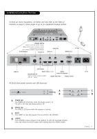
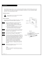
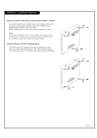
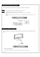
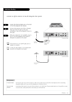
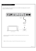
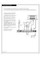
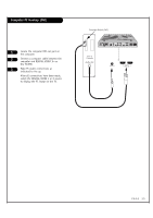
AUX Controller: Connection and Placement Connect the AUX Controller to allow the Integrator Box to operate your AUX device. 1 Connect the AUX Controller to the AUX CONTROL cord on the TV/STB. 2 Place the AUX Controller under and in front of the AUX device. The AUX Controller must extend just out in front of the infrared sensor on the AUX device. *Note: If the infrared sensor is not marked on your AUX device, shine a flashlight into the front panel of the AUX device to locate the sensor. PILLOW INT REMOTE IN PILLOW JACK IN AUX (12V DC 40mA) CONTROL AUDIO IN AUDIO OUT 1 2 DIGITAL VIDEO IN DIGITAL VIDEO OUT DIGITAL AUDIO OUT (OPTICAL) SERVICE AC OUT 8A AC IN 120V~ 60Hz DISPLAY CONTROL Connections Panel DVD (Front View) AUX Controller IR Sensor DVD 1/2" (Side View) to 1" IR Receiver & IR Bracket Installation Install the IR Receiver and Bracket Assembly to the back of the monitor using the method described below. Monitor R AUDIO L (MONO) VIDEO AV INPUT S-VIDEO Y PB PR COM(DPOVDNEINNPTU(4T8)0i/480p) (VGAR/SGVBG-PAC/XIGNAP/USTXGA) R AUDIO L AUDIO INPUT RS-232C (+) R ( ) ( ) L (+) EXTERNAL SPEAKER (8 ) AC INPUT IR Receiver IR Bracket IR Receiver & Bracket Installation PILLOW INT REMOTE IN PILLOW JACK IN AUX (12V DC 40mA) CONTROL AUDIO IN AUDIO OUT 1 2 DIGITAL VIDEO IN DIGITAL VIDEO OUT DIGITAL AUDIO OUT (OPTICAL) SERVICE AC OUT 8A AC IN 120V~ 60Hz DISPLAY CONTROL Connections Panel THE IR RECEIVER UNIT IS PROVIDED. THIS WILL NEED TO BE MOUNTED ON THE MONITOR BACK WITH TWO-SIDED TAPE. PAGE 10
-
 1
1 -
2
-
3
-
4
-
 5
5 -
 6
6 -
 7
7 -
 8
8 -
 9
9 -
 10
10 -
 11
11 -
 12
12 -
 13
13 -
 14
14 -
 15
15 -
16
-
17
-
18
-
19
-
20
-
21
-
22
-
23
-
24
-
25
-
26
-
27
-
28
-
29
-
30
-
31
-
32
-
33
-
34
-
35
-
36
-
37
-
38
-
39
-
40
-
41
-
42
-
43
-
44
-
45
-
46
-
47
-
48
-
49
-
50
-
51
-
52
-
53
-
54
-
55
-
56
-
57
-
58
-
59
-
60
-
61
-
62
-
63
-
64
-
65
-
66
-
67
-
68
-
69
-
70
-
71
-
72
-
73
-
74
-
75
-
76
-
77
-
78
-
79
-
80
 |
 |
