LG HCS5650 Operation Guide - Page 18
Pillow Speaker Setup
 |
View all LG HCS5650 manuals
Add to My Manuals
Save this manual to your list of manuals |
Page 18 highlights
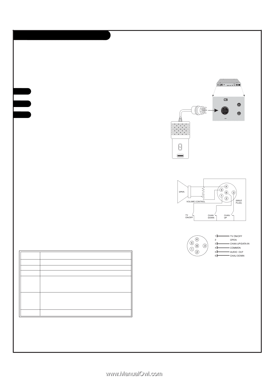
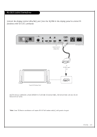
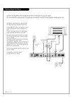
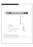
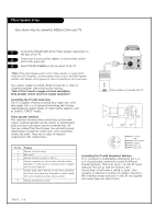
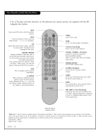
Pillow Speaker Setup Here shown may be somewhat different from your TV. 1 Connect the PILLOW JACK IN the Pillow Speaker output jack on the back of the TV. 2 Connect an accessory pillow speaker or wired remote control unit to this 6-pin jack. 3 Select PILLOW SPEAKER on the rear panel of the TV. *Note: If the pillow Speaker switch is set to Pillow Speaker, no sound will be heard from the TV speakers. If pillow speaker switch is set to the Pillow Speaker position, Auto Volume will be grayed out and not accessible on the Sound menu. Use a pillow speaker by Curbell, Model A-16455-02 or other UL recognized pendant control bearing the warning: "Risk of fire if used in oxygen enriched atmosphere. Keep pendant control away from oxygen equipment." Controlling the TV with Serial Data The TV is capable of being controlled by a single-wire, serial data signal. This is a LG patented technology and is being implemented by certain brands of "smart" pillow speakers, such as Curbell's "GEN-II" models. Pillow Speaker Interface This connector furnishes three control lines and an audio output. A patient-pendant remote control, or entertainment audio and nurse call system may be connected here. All lines are isolated from the AC power line and earth ground. (Optoisolators isolate the control lines, and a transformer isolates the audio. There are no relays or inductive components in the control lines.) RJP INTERFACE REMOTE IN AUX CONTROL AUDIO IN AUDIO OUT 1 2 DIGITAL VIDEO IN DIGITAL VIDEO OUT DIGITAL AUDIO OUT (OPTICAL) RS-232C DISPLAY CONTROL AC OUT AC IN MAX 8A 960W AC 120V~ 60Hz PILLOW INT REMOTE IN PILLOW JACK IN AUX (12V DC 40mA) CONTROL Pillow speaker not included with TV. Pin No. 1 2 3 4 5 Purpose External TV On/Off switch. (Not used.) External Channel Up switch or Data in. Common connection for control, data, and audio output. Impedance to earth ground is a 10-meg resistor in parallel with a 1100 pf capacitor. Isolated audio output. Nominal 14-ohm source impedance with short circuit protection. Intended for a pillow speaker with a low-impedance pad-type volume control. 6 External Channel Down switch. Controlling the TV with Mechanical Switches Pin 4 (common) is momentarily connected to pin 1, 3, or 6 via push-action switches to control On/Off and Channel Up/Down. These pins are at +13 volts DC (when measured from pin 4) with the switches open. Current draw is 8 mA when a switch is closed. (This operation is identical to previous LG models using the 5Wire Interface except that only +7 volts DC was supplied and current draw was only 2.5 mA.) PAGE 18
-
 1
1 -
2
-
3
-
4
-
5
-
6
-
7
-
8
-
9
-
10
-
11
-
12
-
 13
13 -
 14
14 -
 15
15 -
 16
16 -
 17
17 -
 18
18 -
 19
19 -
 20
20 -
 21
21 -
 22
22 -
 23
23 -
24
-
25
-
26
-
27
-
28
-
29
-
30
-
31
-
32
-
33
-
34
-
35
-
36
-
37
-
38
-
39
-
40
-
41
-
42
-
43
-
44
-
45
-
46
-
47
-
48
-
49
-
50
-
51
-
52
-
53
-
54
-
55
-
56
-
57
-
58
-
59
-
60
-
61
-
62
-
63
-
64
-
65
-
66
-
67
-
68
-
69
-
70
-
71
-
72
-
73
-
74
-
75
-
76
-
77
-
78
-
79
-
80
 |
 |