LG HCS5650 Operation Guide - Page 69
TV/STB RS-232 Monitor Requirements / RS-232 Troubleshooting
 |
View all LG HCS5650 manuals
Add to My Manuals
Save this manual to your list of manuals |
Page 69 highlights
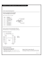
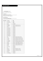
TV/STB RS-232 Monitor Requirements / RS-232 Troubleshooting RS-232 Communication Requirments RS-232 Pin Configuration Wiring Diagram of the TV/STB Display Control Connector Type of Connector; D-Sub 9-Pin Female No. Pin Name 1 No Connection 5 2 TXD (Transmit data) 2 3 RXD (Receive data) 1 4 No Connection 5 GND 6 No Connection 3 7 No Connection 4 8 No Connection 9 No Connection Monitors listed below require RS-232 Null Modem DB9 Cable with male connectors at each end. Depending on the type of Null modem cable, one or two gender changers may be required. RS-232C Null Configuration 3-Wire Configuration (Serial male-male NULL modem cable) TV/STB NC 1 TXD 2 RXD 3 NC 4 GND 5 NC 6 NC 7 NC 8 NC 9 D-Sub 9-pin Male Null-Modem Cable Monitor 1 NC 2 TXD 3 RXD 4 NC 5 GND 6 NC 7 NC 8 NC 9 NC D-Sub 9-pin Male Monitors: M3701-BH M4201-BH RS-232 Troubleshooting Improper RS-232 Communications Setup - Selects Incorrect Source at Power Up TV/STB powers On TV. Flashes selected HDMI/DVI source but selects incorrect Aux source. - Check settings for Installer menu items 108, 109, 110 and 113. - Displays 'No Signal' message at Power Off TV/STB does not power Off TV and displays 'No Signal' message. - Check settings for Installer menu items 108, 109, 110 and 113. PAGE 69
-
 1
1 -
2
-
3
-
4
-
5
-
6
-
7
-
8
-
9
-
10
-
11
-
12
-
13
-
14
-
15
-
16
-
17
-
18
-
19
-
20
-
21
-
22
-
23
-
24
-
25
-
26
-
27
-
28
-
29
-
30
-
31
-
32
-
33
-
34
-
35
-
36
-
37
-
38
-
39
-
40
-
41
-
42
-
43
-
44
-
45
-
46
-
47
-
48
-
49
-
50
-
51
-
52
-
53
-
54
-
55
-
56
-
57
-
58
-
59
-
60
-
61
-
62
-
63
-
 64
64 -
 65
65 -
 66
66 -
 67
67 -
 68
68 -
 69
69 -
 70
70 -
 71
71 -
 72
72 -
 73
73 -
 74
74 -
75
-
76
-
77
-
78
-
79
-
80
 |
 |
