LG HCS5650 Operation Guide - Page 7
Installation/Connections Overview
 |
View all LG HCS5650 manuals
Add to My Manuals
Save this manual to your list of manuals |
Page 7 highlights
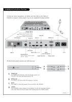
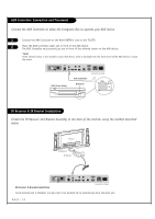
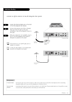
Installation/Connections Overview To hook up source equipment, see below and also refer to the Table of Contents on page 5; shows pages to go to for equipment hookup options. PILLOW INT REMOTE IN PILLOW JACK IN AUX (12V DC 40mA) CONTROL AUDIO IN AUDIO OUT 1 2 DIGITAL VIDEO IN DIGITAL VIDEO OUT DIGITAL AUDIO OUT (OPTICAL) SERVICE DISPLAY CONTROL AC OUT 8A AC IN 120V~60Hz SPEAKER SWITCH Used to select the speaker output. *Note: If Pillow Speaker is selected, no Sound will be heard from TV speakers. Switch (NORMAL SPEAKER or PILLOW SPEAKER.) M.P.I Interface Remote In Audio Out Audio In SERVICE Port AC Out PILLOW INT REMOTE IN PILLOW JACK IN AUX (12V DC 40mA) CONTROL AUDIO IN AUDIO OUT 1 2 DIGITAL VIDEO IN DIGITAL VIDEO OUT DIGITAL AUDIO OUT (OPTICAL) SERVICE DISPLAY CONTROL AC OUT 8A AC IN 120V~60Hz Cable In AUX Control Digital Video 1, 2 In Digital PILLOW JACK IN Audio Out (Optical) Used to connect to pillow speaker (12V DC 40mA) Digital Video Out Display Control AC In HCS5650 front panel controls and LED functions HCS5650 POWER RESET STATUS UPDATE A B POWER RESET STATUS UPDATE A POWER LED The POWER LED illuminates while the display panel is on. The LED is off when the display panel is off. B STATUS LED The STATUS LED flashes while the program is running. C RESET Press RESET to start the program that re-initializes the HCS5650. D UPDATE Press UPDATE to allow software to be updated. To start the download program, press and release the RESET button while holding down the UPDATE button. C D PAGE 7
-
 1
1 -
 2
2 -
 3
3 -
 4
4 -
 5
5 -
 6
6 -
 7
7 -
 8
8 -
 9
9 -
 10
10 -
 11
11 -
 12
12 -
13
-
14
-
15
-
16
-
17
-
18
-
19
-
20
-
21
-
22
-
23
-
24
-
25
-
26
-
27
-
28
-
29
-
30
-
31
-
32
-
33
-
34
-
35
-
36
-
37
-
38
-
39
-
40
-
41
-
42
-
43
-
44
-
45
-
46
-
47
-
48
-
49
-
50
-
51
-
52
-
53
-
54
-
55
-
56
-
57
-
58
-
59
-
60
-
61
-
62
-
63
-
64
-
65
-
66
-
67
-
68
-
69
-
70
-
71
-
72
-
73
-
74
-
75
-
76
-
77
-
78
-
79
-
80
 |
 |
