LG HCS5650 Operation Guide - Page 11
Antenna Hookup
 |
View all LG HCS5650 manuals
Add to My Manuals
Save this manual to your list of manuals |
Page 11 highlights
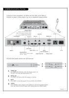
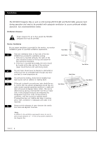
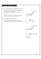
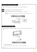
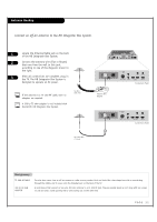
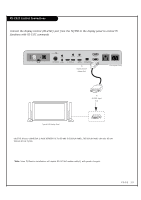
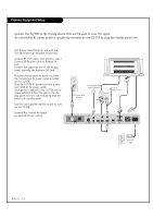
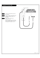
Antenna Hookup Connect an off-air antenna to the HD Integrator Box System. 1 Locate the Antenna/Cable jack on the back of the HD Integrator Box System. 2 Connect the antenna wire (Flat or Round) that runs from the wall to this jack, according to one of the diagrams shown to the right. 3 After all connections are complete, plug in the TV. The HD Integrator Box System is designed to operate on AC power. If the antenna is a 75 ohm RF cable, then no adapters are required. A 300 to 75 ohm adapter is not included with the Zenith HD Integrator Box System. Flat Wire (300 ohm) PILLOW INT REMOTE IN PILLOW JACK IN AUX (12V DC 40mA) CONTROL AUDIO IN AUDIO OUT 1 2 DIGITAL VIDEO IN DIGITAL VIDEO OUT DIGITAL AUDIO OUT (OPTICAL) RS-232C DISPLAY CONTROL AC OUT AC IN MAX 8A 960W AC 120V~ 60Hz 300/75 ohm Adapter PILLOW INT REMOTE IN PILLOW JACK IN AUX (12V DC 40mA) CONTROL AUDIO IN AUDIO OUT 1 2 DIGITAL VIDEO IN DIGITAL VIDEO OUT Connections Panel PILLOW INT REMOTE IN PILLOW JACK IN AUX (12V DC 40mA) CONTROL AUDIO IN AUDIO OUT 1 2 DIGITAL VIDEO IN DIGITAL VIDEO OUT Connections Panel RF Coaxial Wire (75 ohm) Mini glossary 75 OHM RF CABLE 300 TO 75 OHM ADAPTER The wire that comes from an off-air antenna or cable service provider. Each end looks like a hex shaped nut with a wire sticking through the middle, and it screws onto the threaded jack on the back of the TV. A small device that connects a two-wire 300 ohm antenna to a 75 ohm RF jack. They are usually about an inch long with two screws on one end and a round opening with a wire sticking out on the other end. PAGE 11
-
 1
1 -
2
-
3
-
4
-
5
-
 6
6 -
 7
7 -
 8
8 -
 9
9 -
 10
10 -
 11
11 -
 12
12 -
 13
13 -
 14
14 -
 15
15 -
 16
16 -
17
-
18
-
19
-
20
-
21
-
22
-
23
-
24
-
25
-
26
-
27
-
28
-
29
-
30
-
31
-
32
-
33
-
34
-
35
-
36
-
37
-
38
-
39
-
40
-
41
-
42
-
43
-
44
-
45
-
46
-
47
-
48
-
49
-
50
-
51
-
52
-
53
-
54
-
55
-
56
-
57
-
58
-
59
-
60
-
61
-
62
-
63
-
64
-
65
-
66
-
67
-
68
-
69
-
70
-
71
-
72
-
73
-
74
-
75
-
76
-
77
-
78
-
79
-
80
 |
 |
