LG HCS5650 Operation Guide - Page 55
Cloning Connections/Learning Setup
 |
View all LG HCS5650 manuals
Add to My Manuals
Save this manual to your list of manuals |
Page 55 highlights
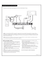
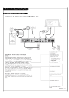
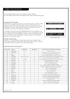
Cloning Connections/Learning Setup Connections for the LT2002 Clone Programmer to Learn the TV/STB Master TV Setup. Ferrite Core (TDK, ZCAT 2035-0930) ¤ QuickSet II Programmer LT2002 3.5mm Stereo Plug with IR Receiver THE CLONE HAS CONTROL OF THE TV THE CLONE IS VERSION XX THE TV IS VERSION XX THE SW IS REVISION XX CLONE CLOCK= TV CLOCK= XX:XX XX:XX -PRESS ANY KEY TO CONTINUE. -DISCONNECT CLONE WHEN DONE. DVI PILLOW INT REMOTE IN PILLOW JACK IN AUX (12V DC 40mA) CONTROL AUDIO IN AUDIO OUT 1 2 DIGITAL VIDEO IN DIGITAL VIDEO OUT DIGITAL AUDIO OUT (OPTICAL) Antenna Wall Jack SERVICE DISPLAY CONTROL AC OUT 8A AC IN 120V~ 60Hz RF Coaxial Wire (75ohm) AC Power Cord *Notes: It is assumed that the TV/STB is connected to a signal source, the source selected is Antenna (RF) In, the signal is from an Analog channel, not a digital channel, all equipment is connected to power and turned on and the LT2002 Clone Programmer main menu (THE CLONE HAS CONTROL OF THE TV) menu is displayed on the TV screen, the clone programmer LED is blinking the required heart beat pattern, see above and next page. *Notes: Once the clone is connected, do not touch the unit or otherwise disturb it or the MPI connections. Any disturbance while the clone is operating may disrupt the master setup transfer or copying etc. Before you begin cloning... • The Master TV/STB should be connected to a good, stable signal from an over-the-air antenna or cable service Analog channel and connected to power. (See above.) • Teaching and Learning is only possible between identical model devices. (However, the LT2002 Clone programmer can store up to 3 different 'master' setups.) WARNING: Copying a blank or incorrect memory into a TV, STB or other device will cause the TV, STB or other device to operate erratically or become inoperable. • Use an Installer's remote to operate Learning and Teaching menus. • Make sure that the batteries in the Clone programmer are fresh. • If batteries are removed, the Clone Clock time will be lost. • Decide if you want to set the time from the Clone programmer TV which has the clock set to the current time. • Setting the time and transferring it to the Clone or other device is a separate procedure. • Follow the connection diagram above to connect the Clone to a Master TV/STB display panel. After learning is complete, to another identical TV/STB display panel to "teach" it the master setup. • After the TV/STB setup has been copied to another identical TV/STB, that identical unit with the copied setup, needs to be disconnected from power for about 15 seconds to activate the newly-copied setup. • See the Clone Troubleshooting section to resolve problems. Turn to the next page to continue Cloning Setup. PAGE 55
-
 1
1 -
2
-
3
-
4
-
5
-
6
-
7
-
8
-
9
-
10
-
11
-
12
-
13
-
14
-
15
-
16
-
17
-
18
-
19
-
20
-
21
-
22
-
23
-
24
-
25
-
26
-
27
-
28
-
29
-
30
-
31
-
32
-
33
-
34
-
35
-
36
-
37
-
38
-
39
-
40
-
41
-
42
-
43
-
44
-
45
-
46
-
47
-
48
-
49
-
 50
50 -
 51
51 -
 52
52 -
 53
53 -
 54
54 -
 55
55 -
 56
56 -
 57
57 -
 58
58 -
 59
59 -
 60
60 -
61
-
62
-
63
-
64
-
65
-
66
-
67
-
68
-
69
-
70
-
71
-
72
-
73
-
74
-
75
-
76
-
77
-
78
-
79
-
80
 |
 |
