Lantronix SpiderDuo Lantronix Spider / SpiderDuo - User Guide - Page 26
Installing the Spider Device, Spider™ and SpiderDuo® KVM-over-IP Device User Guide,
 |
View all Lantronix SpiderDuo manuals
Add to My Manuals
Save this manual to your list of manuals |
Page 26 highlights
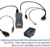
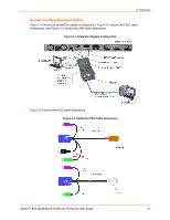
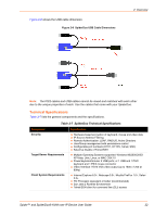
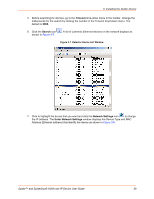
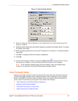
3: Installing the Spider Device Ethernet Ports-Connects to the LAN. The Spider device contains a hardware Ethernet switch that connects to the external ports and an internal CPU. The first port is required for network connection. The second port can be used for the following: - Tie all of the Spider units in a rack together so that one network connection only is required. While this configuration is a "daisy" chain physically, logically each Spider device has its own IP address on the network. Because the Spider device data that comes from the end of the chain traverses all of the switches, latency increases and responsiveness degrades depending on the number of devices in the chain. Lantronix recommends a maximum of 16 Spider devices in a chain. But, if the network switch that connects to the Spider device chain supports Spanning Tree, the first and last devices in the chain can connect to the same network switch to provide resilience against a single-point failure. - Connect to the LAN management port on the server, so that an external management network can interface to the Spider device and the server by using one cable. - Connect to the main LAN port on the server. If physical isolation of management and user data is not a concern, a single LAN cable can provide connectivity to the Spider device and server conserving a switch or router port. - Aggregate any other Ethernet connection as a general-purpose switch port. Batch vs. Individual Setup-Deploying a batch of Spider devices at once should be performed as a stage before attaching to the computers. The staging can be performed on a bench prior to configuration. Consider the following tips for configuring a batch of Spider devices: - Keyboard, video, and mouse connections are not required for setup. All you need are a source of power and a serial connection to set up the network parameters, and an Ethernet connection to access the administration user interface. - Tag each Spider device with its IP address or write it on the serial number label on the bottom. Perform the following steps to install the Spider device and configure the initial network settings. 1. Plug the RJ45 cable into the Spider serial port which is shown in Figure 3-1. The RS-232 protocol is the standard for serial binary data signals. Figure 3-1 Spider RS-232 Serial Port and Pinouts Pinouts 1 RTS 2 DTR 3 TX 4 GND 5 GND 6 RX 7 DSR 8 CTS (out) (out) (out) (in) (in) (in) 2. Plug the DB9F cable into the serial (COM) port of a PC or laptop running a terminal emulator, for example, HyperTerminal. The default serial port settings are: 9600 bits per second, 8 data bits, no parity, 1 stop bit, no flow control. 3. Plug the Spider video, USB, and PS/2 keyboard and mouse cables into the target computer. The Spider device boots. Spider™ and SpiderDuo® KVM-over-IP Device User Guide 26
-
 1
1 -
2
-
3
-
4
-
5
-
6
-
7
-
8
-
9
-
10
-
11
-
12
-
13
-
14
-
15
-
16
-
17
-
18
-
19
-
20
-
 21
21 -
 22
22 -
 23
23 -
 24
24 -
 25
25 -
 26
26 -
 27
27 -
 28
28 -
 29
29 -
 30
30 -
 31
31 -
32
-
33
-
34
-
35
-
36
-
37
-
38
-
39
-
40
-
41
-
42
-
43
-
44
-
45
-
46
-
47
-
48
-
49
-
50
-
51
-
52
-
53
-
54
-
55
-
56
-
57
-
58
-
59
-
60
-
61
-
62
-
63
-
64
-
65
-
66
-
67
-
68
-
69
-
70
-
71
-
72
-
73
-
74
-
75
-
76
-
77
-
78
-
79
-
80
-
81
-
82
-
83
-
84
-
85
-
86
-
87
-
88
-
89
-
90
-
91
-
92
-
93
-
94
-
95
-
96
-
97
-
98
-
99
-
100
-
101
-
102
-
103
-
104
-
105
-
106
-
107
-
108
-
109
-
110
-
111
-
112
-
113
-
114
-
115
-
116
-
117
-
118
-
119
-
120
-
121
-
122
-
123
-
124
-
125
-
126
-
127
-
128
-
129
-
130
-
131
-
132
-
133
 |
 |
