Lenovo ThinkCentre A70 (English) User Guide - Page 18
Locating components, remove the computer cover and gain access to the inside of the computer, see
 |
View all Lenovo ThinkCentre A70 manuals
Add to My Manuals
Save this manual to your list of manuals |
Page 18 highlights
Locating components Figure 3 shows the locations of the various components in your computer. To remove the computer cover and gain access to the inside of the computer, see "Removing the computer cover" on page 14. Figure 3. Component locations 1 Heat sink and fan assembly 2 Memory modules (2) 3 Battery 4 PCI card slot 5 PCI Express x16 graphics card (available in some models) 6 PCI Express x1 card slots (2) 7 PCI Express x16 graphics card slot 8 Power supply assembly 10 User Guide
-
 1
1 -
2
-
3
-
4
-
5
-
6
-
7
-
8
-
9
-
10
-
11
-
12
-
 13
13 -
 14
14 -
 15
15 -
 16
16 -
 17
17 -
 18
18 -
 19
19 -
 20
20 -
 21
21 -
 22
22 -
 23
23 -
24
-
25
-
26
-
27
-
28
-
29
-
30
-
31
-
32
-
33
-
34
-
35
-
36
-
37
-
38
-
39
-
40
-
41
-
42
-
43
-
44
-
45
-
46
-
47
-
48
-
49
-
50
-
51
-
52
-
53
-
54
-
55
-
56
-
57
-
58
-
59
-
60
-
61
-
62
-
63
-
64
-
65
-
66
-
67
-
68
-
69
-
70
-
71
-
72
-
73
-
74
-
75
-
76
-
77
-
78
-
79
-
80
-
81
-
82
-
83
-
84
 |
 |
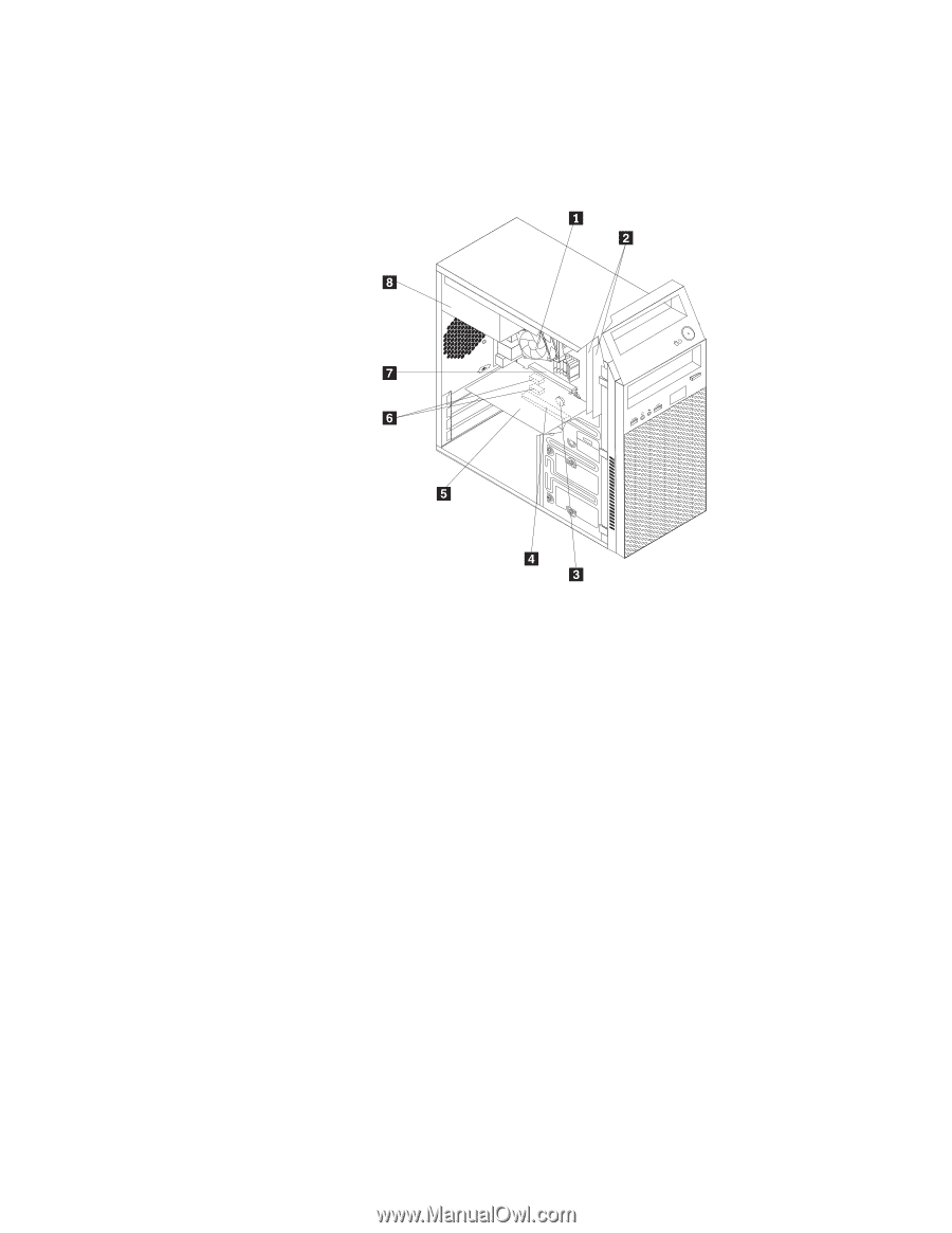
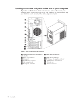
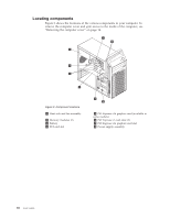
Locating components
Figure 3 shows the locations of the various components in your computer. To
remove the computer cover and gain access to the inside of the computer, see
“Removing the computer cover” on page 14.
±1²
Heat sink and fan assembly
±5²
PCI Express x16 graphics card (available in
some models)
±2²
Memory modules (2)
±6²
PCI Express x1 card slots (2)
±3²
Battery
±7²
PCI Express x16 graphics card slot
±4²
PCI card slot
±8²
Power supply assembly
Figure 3. Component locations
10
User Guide