Lenovo ThinkCentre A70 (English) User Guide - Page 34
Notes, you can easily connect the new heat sink and fan assembly cable to
 |
View all Lenovo ThinkCentre A70 manuals
Add to My Manuals
Save this manual to your list of manuals |
Page 34 highlights
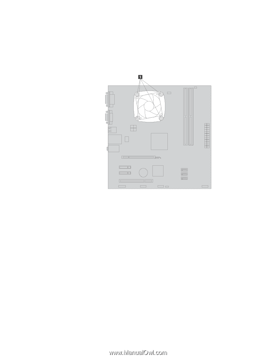
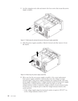
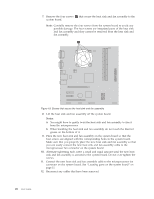
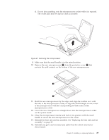
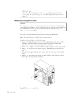
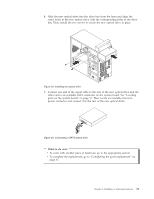
7. Remove the four screws 1 that secure the heat sink and fan assembly to the system board. Note: Carefully remove the four screws from the system board to avoid any possible damage. The four screws are integrated parts of the heat sink and fan assembly and they cannot be removed from the heat sink and fan assembly. Figure 19. Screws that secure the heat sink and fan assembly 8. Lift the heat sink and fan assembly off the system board. Notes: a. You might have to gently twist the heat sink and fan assembly to free it from the microprocessor. b. When handling the heat sink and fan assembly, do not touch the thermal grease on the bottom of it. 9. Place the new heat sink and fan assembly on the system board so that the four screws are aligned with the corresponding holes in the system board. Make sure that you properly place the new heat sink and fan assembly so that you can easily connect the new heat sink and fan assembly cable to the microprocessor fan connector on the system board. 10. Alternate tightening each screw a small and equal amount until the new heat sink and fan assembly is secured to the system board. Do not over-tighten the screws. 11. Connect the new heat sink and fan assembly cable to the microprocessor fan connector on the system board. See "Locating parts on the system board" on page 11. 12. Reconnect any cables that have been removed. 26 User Guide
-
 1
1 -
2
-
3
-
4
-
5
-
6
-
7
-
8
-
9
-
10
-
11
-
12
-
13
-
14
-
15
-
16
-
17
-
18
-
19
-
20
-
21
-
22
-
23
-
24
-
25
-
26
-
27
-
28
-
 29
29 -
 30
30 -
 31
31 -
 32
32 -
 33
33 -
 34
34 -
 35
35 -
 36
36 -
 37
37 -
 38
38 -
 39
39 -
40
-
41
-
42
-
43
-
44
-
45
-
46
-
47
-
48
-
49
-
50
-
51
-
52
-
53
-
54
-
55
-
56
-
57
-
58
-
59
-
60
-
61
-
62
-
63
-
64
-
65
-
66
-
67
-
68
-
69
-
70
-
71
-
72
-
73
-
74
-
75
-
76
-
77
-
78
-
79
-
80
-
81
-
82
-
83
-
84
 |
 |