Lenovo ThinkPad W701 Hardware Maintenance Manual - Page 121
Table 41. Removal steps of LCD unit for W700 and W700ds continued
 |
View all Lenovo ThinkPad W701 manuals
Add to My Manuals
Save this manual to your list of manuals |
Page 121 highlights
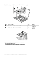
Table 41. Removal steps of LCD unit for W700 and W700ds (continued) 7 7 When installing: 1. Route the antenna cables along the cable guides and secure them with the tapes. As you route the cables, make sure that they are not subjected to any tension. Tension could cause the cables to be damaged by the cable guides, or a wire to be broken. 2. Make sure that the LCD connector is attached firmly. Table 42. Removal steps of LCD unit for W701 and W701ds For ThinkPad W701 and W701ds: Chapter 9. Removing and replacing a FRU 115
-
 1
1 -
2
-
3
-
4
-
5
-
6
-
7
-
8
-
9
-
10
-
11
-
12
-
13
-
14
-
15
-
16
-
17
-
18
-
19
-
20
-
21
-
22
-
23
-
24
-
25
-
26
-
27
-
28
-
29
-
30
-
31
-
32
-
33
-
34
-
35
-
36
-
37
-
38
-
39
-
40
-
41
-
42
-
43
-
44
-
45
-
46
-
47
-
48
-
49
-
50
-
51
-
52
-
53
-
54
-
55
-
56
-
57
-
58
-
59
-
60
-
61
-
62
-
63
-
64
-
65
-
66
-
67
-
68
-
69
-
70
-
71
-
72
-
73
-
74
-
75
-
76
-
77
-
78
-
79
-
80
-
81
-
82
-
83
-
84
-
85
-
86
-
87
-
88
-
89
-
90
-
91
-
92
-
93
-
94
-
95
-
96
-
97
-
98
-
99
-
100
-
101
-
102
-
103
-
104
-
105
-
106
-
107
-
108
-
109
-
110
-
111
-
112
-
113
-
114
-
115
-
 116
116 -
 117
117 -
 118
118 -
 119
119 -
 120
120 -
 121
121 -
 122
122 -
 123
123 -
 124
124 -
 125
125 -
 126
126 -
127
-
128
-
129
-
130
-
131
-
132
-
133
-
134
-
135
-
136
-
137
-
138
-
139
-
140
-
141
-
142
-
143
-
144
-
145
-
146
-
147
-
148
-
149
-
150
-
151
-
152
-
153
-
154
-
155
-
156
-
157
-
158
-
159
-
160
-
161
-
162
-
163
-
164
-
165
-
166
-
167
-
168
-
169
-
170
-
171
-
172
-
173
-
174
-
175
-
176
-
177
-
178
-
179
-
180
-
181
-
182
-
183
-
184
-
185
-
186
-
187
-
188
-
189
-
190
-
191
-
192
-
193
-
194
-
195
-
196
-
197
-
198
-
199
-
200
-
201
-
202
-
203
-
204
-
205
-
206
-
207
-
208
-
209
-
210
-
211
-
212
-
213
-
214
-
215
-
216
-
217
-
218
 |
 |
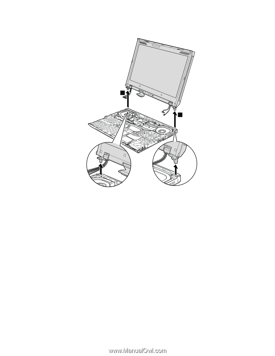
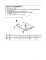
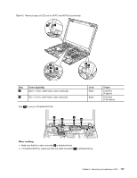
Table 41. Removal steps of LCD unit for W700 and W700ds (continued)
7
7
When installing:
1. Route the antenna cables along the cable guides and secure them with the tapes. As you route the cables,
make sure that they are not subjected to any tension. Tension could cause the cables to be damaged by
the cable guides, or a wire to be broken.
2. Make sure that the LCD connector is attached firmly.
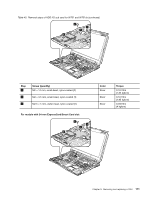
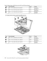
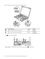
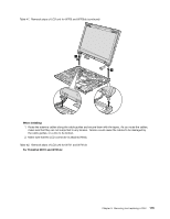
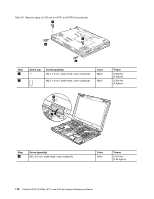
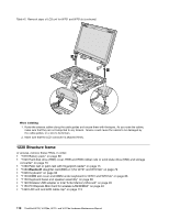
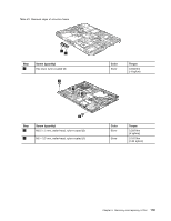
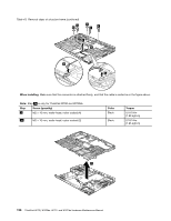
Table 42. Removal steps of LCD unit for W701 and W701ds
For ThinkPad W701 and W701ds:
Chapter 9
.
Removing and replacing a FRU
115