Lenovo ThinkPad W701 Hardware Maintenance Manual - Page 94
Keyboard bezel and speaker assembly
 |
View all Lenovo ThinkPad W701 manuals
Add to My Manuals
Save this manual to your list of manuals |
Page 94 highlights
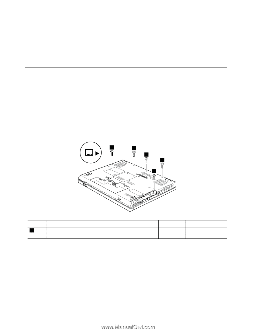
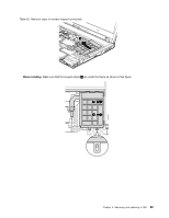
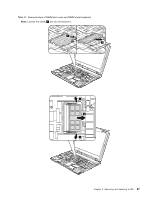
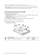
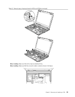
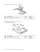
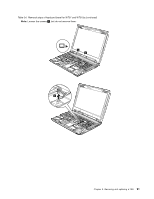
Table 21. Removal steps of DIMM slot cover and DIMM under keyboard (continued) Note: If only one DIMM is used on the computer you are servicing, the card must be installed in the lower slot. When installing: Insert the notched end of the DIMM into the socket. Press the DIMM firmly, and pivot it until it snaps into the place. Make sure that it is firmly fixed in the slot and does not move easily. 1130 Keyboard bezel and speaker assembly For access, remove these FRUs in order: • "1010 Battery pack" on page 68 • "1040 Hard disk drive (HDD) cover, HDD and HDD rubber rails or solid state drive (SSD) and storage converter" on page 70 • "1060 Palm rest or palm rest with fingerprint reader" on page 75 • "1090 Keyboard" on page 80 • "1120 DIMM slot cover and DIMM under keyboard for W701 and W701ds" on page 86 Note: Speaker assembly is attached to the keyboard bezel. Table 22. Removal steps of keyboard bezel for W700 and W700ds For ThinkPad W700 and W700ds: 1 1 1 1 1 Step 1 Screw (quantity) M2.5 × 9 mm, wafer-head, nylon-coated (5) Color Black Torque 0.392 Nm (4 kgfcm) 88 ThinkPad W700, W700ds, W701, and W701ds Hardware Maintenance Manual
-
 1
1 -
2
-
3
-
4
-
5
-
6
-
7
-
8
-
9
-
10
-
11
-
12
-
13
-
14
-
15
-
16
-
17
-
18
-
19
-
20
-
21
-
22
-
23
-
24
-
25
-
26
-
27
-
28
-
29
-
30
-
31
-
32
-
33
-
34
-
35
-
36
-
37
-
38
-
39
-
40
-
41
-
42
-
43
-
44
-
45
-
46
-
47
-
48
-
49
-
50
-
51
-
52
-
53
-
54
-
55
-
56
-
57
-
58
-
59
-
60
-
61
-
62
-
63
-
64
-
65
-
66
-
67
-
68
-
69
-
70
-
71
-
72
-
73
-
74
-
75
-
76
-
77
-
78
-
79
-
80
-
81
-
82
-
83
-
84
-
85
-
86
-
87
-
88
-
 89
89 -
 90
90 -
 91
91 -
 92
92 -
 93
93 -
 94
94 -
 95
95 -
 96
96 -
 97
97 -
 98
98 -
 99
99 -
100
-
101
-
102
-
103
-
104
-
105
-
106
-
107
-
108
-
109
-
110
-
111
-
112
-
113
-
114
-
115
-
116
-
117
-
118
-
119
-
120
-
121
-
122
-
123
-
124
-
125
-
126
-
127
-
128
-
129
-
130
-
131
-
132
-
133
-
134
-
135
-
136
-
137
-
138
-
139
-
140
-
141
-
142
-
143
-
144
-
145
-
146
-
147
-
148
-
149
-
150
-
151
-
152
-
153
-
154
-
155
-
156
-
157
-
158
-
159
-
160
-
161
-
162
-
163
-
164
-
165
-
166
-
167
-
168
-
169
-
170
-
171
-
172
-
173
-
174
-
175
-
176
-
177
-
178
-
179
-
180
-
181
-
182
-
183
-
184
-
185
-
186
-
187
-
188
-
189
-
190
-
191
-
192
-
193
-
194
-
195
-
196
-
197
-
198
-
199
-
200
-
201
-
202
-
203
-
204
-
205
-
206
-
207
-
208
-
209
-
210
-
211
-
212
-
213
-
214
-
215
-
216
-
217
-
218
 |
 |