Lenovo ThinkPad W701 Hardware Maintenance Manual - Page 81
Palm rest or palm rest with fingerprint reader, 1040 Hard disk drive HDD cover
 |
View all Lenovo ThinkPad W701 manuals
Add to My Manuals
Save this manual to your list of manuals |
Page 81 highlights
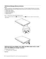
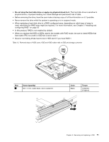
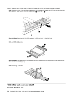
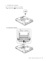
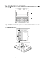
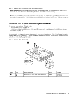
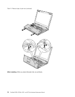
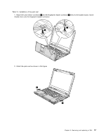
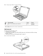
Table 13. Removal steps of DIMM slot cover and DIMM (continued) When installing: Insert the notched end of the DIMM into the socket. Press the DIMM firmly, and pivot it until it snaps into the place. Make sure that it is firmly fixed in the slot and does not move easily. Note: If only one DIMM is used on the computer you are servicing, the card must be installed in the lower slot of the slots under the keyboard. See "1120 DIMM slot cover and DIMM under keyboard for W701 and W701ds" on page 86. 1060 Palm rest or palm rest with fingerprint reader For access, remove these FRUs in order: • "1010 Battery pack" on page 68 • "1040 Hard disk drive (HDD) cover, HDD and HDD rubber rails or solid state drive (SSD) and storage converter" on page 70 Note: In models with the fingerprint reader, the sensor is attached to the palm rest FRU. If the fingerprint reader has any defects, you can replace it by the procedures given in this section, which are the same for a palm rest with or without a fingerprint reader. Table 14. Removal steps of palm rest 1 1 1 1 Step 1 Icon Screw (quantity) M2.5 × 9 mm, wafer-head, nylon-coated (4) Color Black Torque 0.392 Nm (4 kgfcm) Chapter 9. Removing and replacing a FRU 75
-
 1
1 -
2
-
3
-
4
-
5
-
6
-
7
-
8
-
9
-
10
-
11
-
12
-
13
-
14
-
15
-
16
-
17
-
18
-
19
-
20
-
21
-
22
-
23
-
24
-
25
-
26
-
27
-
28
-
29
-
30
-
31
-
32
-
33
-
34
-
35
-
36
-
37
-
38
-
39
-
40
-
41
-
42
-
43
-
44
-
45
-
46
-
47
-
48
-
49
-
50
-
51
-
52
-
53
-
54
-
55
-
56
-
57
-
58
-
59
-
60
-
61
-
62
-
63
-
64
-
65
-
66
-
67
-
68
-
69
-
70
-
71
-
72
-
73
-
74
-
75
-
 76
76 -
 77
77 -
 78
78 -
 79
79 -
 80
80 -
 81
81 -
 82
82 -
 83
83 -
 84
84 -
 85
85 -
 86
86 -
87
-
88
-
89
-
90
-
91
-
92
-
93
-
94
-
95
-
96
-
97
-
98
-
99
-
100
-
101
-
102
-
103
-
104
-
105
-
106
-
107
-
108
-
109
-
110
-
111
-
112
-
113
-
114
-
115
-
116
-
117
-
118
-
119
-
120
-
121
-
122
-
123
-
124
-
125
-
126
-
127
-
128
-
129
-
130
-
131
-
132
-
133
-
134
-
135
-
136
-
137
-
138
-
139
-
140
-
141
-
142
-
143
-
144
-
145
-
146
-
147
-
148
-
149
-
150
-
151
-
152
-
153
-
154
-
155
-
156
-
157
-
158
-
159
-
160
-
161
-
162
-
163
-
164
-
165
-
166
-
167
-
168
-
169
-
170
-
171
-
172
-
173
-
174
-
175
-
176
-
177
-
178
-
179
-
180
-
181
-
182
-
183
-
184
-
185
-
186
-
187
-
188
-
189
-
190
-
191
-
192
-
193
-
194
-
195
-
196
-
197
-
198
-
199
-
200
-
201
-
202
-
203
-
204
-
205
-
206
-
207
-
208
-
209
-
210
-
211
-
212
-
213
-
214
-
215
-
216
-
217
-
218
 |
 |