Lenovo ThinkPad W701 Hardware Maintenance Manual - Page 124
Structure frame
 |
View all Lenovo ThinkPad W701 manuals
Add to My Manuals
Save this manual to your list of manuals |
Page 124 highlights
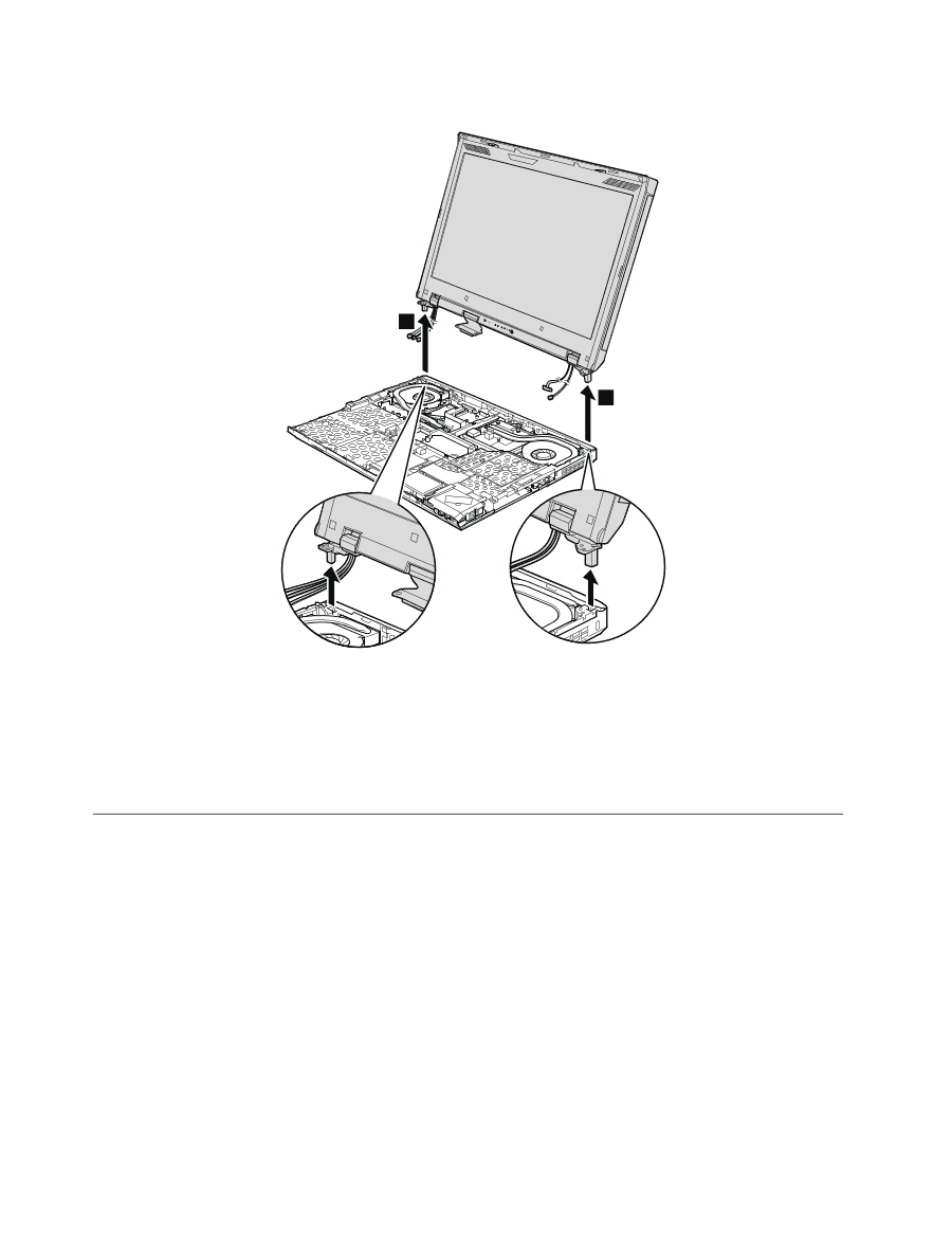
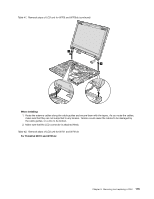
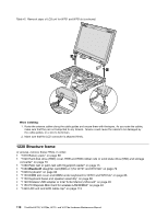
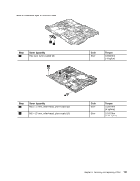
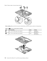
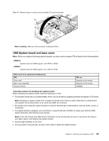
Table 42. Removal steps of LCD unit for W701 and W701ds (continued) 10 10 When installing: 1. Route the antenna cables along the cable guides and secure them with the tapes. As you route the cables, make sure that they are not subjected to any tension. Tension could cause the cables to be damaged by the cable guides, or a wire to be broken. 2. Make sure that the LCD connector is attached firmly. 1230 Structure frame or access, remove these FRUs, in order: • "1010 Battery pack" on page 68 • "1040 Hard disk drive (HDD) cover, HDD and HDD rubber rails or solid state drive (SSD) and storage converter" on page 70 • "1060 Palm rest or palm rest with fingerprint reader" on page 75 • "1080 Bluetooth daughter card (BDC-2.1) for W701 and W701ds" on page 79 • "1090 Keyboard" on page 80 • "1120 DIMM slot cover and DIMM under keyboard for W701 and W701ds" on page 86 • "1130 Keyboard bezel and speaker assembly" on page 88 • "1140 Wireless USB adapter or Intel Turbo Memory Minicard" on page 93 • "1150 PCI Express Mini Card for wireless LAN/WiMAX" on page 94 • "1220 LCD unit and LCD cable cap" on page 113 118 ThinkPad W700, W700ds, W701, and W701ds Hardware Maintenance Manual
-
 1
1 -
2
-
3
-
4
-
5
-
6
-
7
-
8
-
9
-
10
-
11
-
12
-
13
-
14
-
15
-
16
-
17
-
18
-
19
-
20
-
21
-
22
-
23
-
24
-
25
-
26
-
27
-
28
-
29
-
30
-
31
-
32
-
33
-
34
-
35
-
36
-
37
-
38
-
39
-
40
-
41
-
42
-
43
-
44
-
45
-
46
-
47
-
48
-
49
-
50
-
51
-
52
-
53
-
54
-
55
-
56
-
57
-
58
-
59
-
60
-
61
-
62
-
63
-
64
-
65
-
66
-
67
-
68
-
69
-
70
-
71
-
72
-
73
-
74
-
75
-
76
-
77
-
78
-
79
-
80
-
81
-
82
-
83
-
84
-
85
-
86
-
87
-
88
-
89
-
90
-
91
-
92
-
93
-
94
-
95
-
96
-
97
-
98
-
99
-
100
-
101
-
102
-
103
-
104
-
105
-
106
-
107
-
108
-
109
-
110
-
111
-
112
-
113
-
114
-
115
-
116
-
117
-
118
-
 119
119 -
 120
120 -
 121
121 -
 122
122 -
 123
123 -
 124
124 -
 125
125 -
 126
126 -
 127
127 -
 128
128 -
 129
129 -
130
-
131
-
132
-
133
-
134
-
135
-
136
-
137
-
138
-
139
-
140
-
141
-
142
-
143
-
144
-
145
-
146
-
147
-
148
-
149
-
150
-
151
-
152
-
153
-
154
-
155
-
156
-
157
-
158
-
159
-
160
-
161
-
162
-
163
-
164
-
165
-
166
-
167
-
168
-
169
-
170
-
171
-
172
-
173
-
174
-
175
-
176
-
177
-
178
-
179
-
180
-
181
-
182
-
183
-
184
-
185
-
186
-
187
-
188
-
189
-
190
-
191
-
192
-
193
-
194
-
195
-
196
-
197
-
198
-
199
-
200
-
201
-
202
-
203
-
204
-
205
-
206
-
207
-
208
-
209
-
210
-
211
-
212
-
213
-
214
-
215
-
216
-
217
-
218
 |
 |