Linksys BEFSR11 User Guide - Page 13
Connect the Router - setup
 |
UPC - 745883549405
View all Linksys BEFSR11 manuals
Add to My Manuals
Save this manual to your list of manuals |
Page 13 highlights
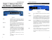
Instant Broadband™ Series Chapter 5: Connect the Router Overview Unlike a hub or a switch, the Cable/DSL Router's setup consists of more than simply plugging hardware together. You will have to configure your networked PCs to accept the IP addresses that the Router assigns them (if applicable), and you will also have to configure the Router with setting(s) provided by your Internet Service Provider (ISP). The installation technician from your ISP should have left the setup information with you after installing your broadband connection. If not, you can call your ISP to request the data. Once you have the setup information you need for your specific type of Internet connection, you can begin installation and setup of the Router. WAN Cable or DSL Modem Notebook with Ethernet Adapter Cable/DSL Router PC with Ethernet Adapter Figure 5-1 LAN 18 EtherFast® Cable/DSL Routers Connecting Your Hardware Together and Booting Up 1. Before you begin, make sure that all of your hardware is powered off, including the Router, PCs, hubs, switches, and cable or DSL modem. 2. If you have the 4-Port Router, go to step 2.A. If you have the 1-Port Router, go to step 2.B. If you have the 3-Port Router, go to step 2.C. 2. A. If you have the 4-Port Cable/DSL Router, connect one end of an Ethernet cable to one of the LAN ports (labeled 1, 2, 3, or 4) on the back of the Router, and the other end to a standard port on a network device, e.g., a PC, print server, hub, or switch. See "Appendix E: Twisted-Pair Cabling" for details on network cabling. Note: A standard port is any port other than the WAN port and the Uplink port on the Router. It is a straight-through port. Repeat the above step to connect more PCs or network devices to the Router. 2. B. If you have the 1-Port Router, connect one end of an Ethernet cable to the LAN port on the back of the Router, and the other end to a port on a network device, e.g., a PC, hub, or switch. If you are using the LAN Port to con- nect to a PC, set the Crossover switch to straight-through mode ( || ). If you are connecting the Router to a hub or switch, refer to the chart shown in Figure 5-2 when setting the Crossover switch. Figure 5-2 2. C. If you have the 3-Port Cable/DSL Router, connect one end of an Ethernet cable from the Router's LAN ports (labeled 1, 2, or 3) to an Ethernet adapter port on a PC, hub, switch, or other network device. The 3-Port Router features one USB plug-and-play port that connects instantly to any USB-ready PC or USB hub. This allows you to connect to and access the Router without even installing any Ethernet adapter cards. 19
-
 1
1 -
2
-
3
-
4
-
5
-
6
-
7
-
 8
8 -
 9
9 -
 10
10 -
 11
11 -
 12
12 -
 13
13 -
 14
14 -
 15
15 -
 16
16 -
 17
17 -
 18
18 -
19
-
20
-
21
-
22
-
23
-
24
-
25
-
26
-
27
-
28
-
29
-
30
-
31
-
32
-
33
-
34
-
35
-
36
-
37
-
38
-
39
-
40
-
41
-
42
-
43
-
44
-
45
-
46
-
47
-
48
-
49
-
50
-
51
-
52
-
53
-
54
-
55
-
56
-
57
-
58
-
59
-
60
-
61
-
62
-
63
-
64
-
65
-
66
 |
 |
