Linksys RTP300 User Guide - Page 21
Linksys SPA8000 Connectivity - default ip
 |
UPC - 745883565658
View all Linksys RTP300 manuals
Add to My Manuals
Save this manual to your list of manuals |
Page 21 highlights
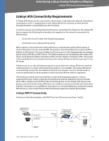
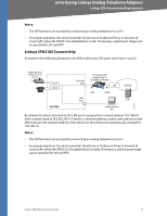
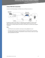
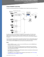
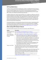
Introducing Linksys Analog Telephone Adapters Linksys ATA Connectivity Requirements Linksys SPA8000 Connectivity As shown in the following illustration, the SPA8000 consists of eight voice ports (voice lines 1-8). Administrative IVR (Line 1 or Line 2) 8 FXS (RJ-11/RJ-21 ) ports SPA8000 Line 1 NAT/PAT Internal DHCP Line 2 server Ethernet port Line 3 Line 4 AUX port IP Router (with hairpinning) or Broadband modem ISP LAN WAN Administration PC Internet IP ITSP Line 5 Line 6 Line 7 Line 8 187256 By default, the device on the AUX port is assigned the network address 192.168.0.0 with a subnet mask of 255.255.255.0. If there is a network address conflict with a device on the Ethernet port, the network address of the device on the AUX port is automatically changed to 192.168.1.0. In the illustration, one fax machine is connected to each pair of ports to illustrate that only one T.38 connection is supported by each of the four pairs of RJ-11 ports. Up to four fax machines can be connected to the SPA8000 router, but they must be distributed as shown. Notes: • With the SPA8000, use line 1 or line 2 to access the IVR functions. See the SPA8000 Quick Installation Guide for IVR instructions. • For proper operation, the service provider should use an Outbound Proxy to forward all voice traffic when the SPA8000 is located behind a router. If necessary, explicit port ranges can be specified for SIP and RTP. • The SPA8000 is not designed to forward IP packets to devices connected to its AUX port and that configuration is not supported. • The SPA8000 also can be configured with trunk groups and trunk lines. See "SIP Trunking and Hunt Groups on the SPA8000," on page 61. Linksys ATA Administration Guide 21
-
 1
1 -
2
-
3
-
4
-
5
-
6
-
7
-
8
-
9
-
10
-
11
-
12
-
13
-
14
-
15
-
 16
16 -
 17
17 -
 18
18 -
 19
19 -
 20
20 -
 21
21 -
 22
22 -
 23
23 -
 24
24 -
 25
25 -
 26
26 -
27
-
28
-
29
-
30
-
31
-
32
-
33
-
34
-
35
-
36
-
37
-
38
-
39
-
40
-
41
-
42
-
43
-
44
-
45
-
46
-
47
-
48
-
49
-
50
-
51
-
52
-
53
-
54
-
55
-
56
-
57
-
58
-
59
-
60
-
61
-
62
-
63
-
64
-
65
-
66
-
67
-
68
-
69
-
70
-
71
-
72
-
73
-
74
-
75
-
76
-
77
-
78
-
79
-
80
-
81
-
82
-
83
-
84
-
85
-
86
-
87
-
88
-
89
-
90
-
91
-
92
-
93
-
94
-
95
-
96
-
97
-
98
-
99
-
100
-
101
-
102
-
103
-
104
-
105
-
106
-
107
-
108
-
109
-
110
-
111
-
112
-
113
-
114
-
115
-
116
-
117
-
118
-
119
-
120
-
121
-
122
-
123
-
124
-
125
-
126
-
127
-
128
-
129
-
130
-
131
-
132
-
133
-
134
-
135
-
136
-
137
-
138
-
139
-
140
-
141
-
142
-
143
-
144
-
145
-
146
-
147
-
148
-
149
-
150
-
151
-
152
-
153
-
154
-
155
-
156
-
157
-
158
-
159
-
160
-
161
-
162
-
163
-
164
-
165
-
166
-
167
-
168
-
169
-
170
-
171
-
172
-
173
-
174
-
175
-
176
-
177
-
178
-
179
-
180
-
181
-
182
-
183
-
184
-
185
-
186
-
187
-
188
-
189
-
190
-
191
-
192
-
193
-
194
-
195
-
196
-
197
-
198
-
199
-
200
-
201
 |
 |
