Lowrance HDS-7 LIVE HDS Live Operator Manual - Page 95
Setting up the image, Source, Range, You can display different sources simultaneously, using a multi
 |
View all Lowrance HDS-7 LIVE manuals
Add to My Manuals
Save this manual to your list of manuals |
Page 95 highlights
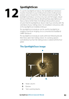
3. Move the position adjustment scroll bar so the top of the V in the image is centered at the top of the panel. Ú Note: The V on the image represents the beams of the SpotlightScan transducer. The wide end of the V should be aligned in the direction the trolling motor is pointing. Ú Note: Do not use the arrow indicator on the trolling motor head as a heading reference as it might not be aligned correctly with the trolling motor. Setting up the image Source Ú Note: Available only if multiple sources with the same capability are available. Used to specify the source for the image in the active panel. You can display different sources simultaneously, using a multipanel page configuration. Menu options for each panel are independent. Ú Note: Using transducers at the same frequency can cause interference. For source setup information, refer to the HDS Live Installation Manual. Range You can control how much of the area around your boat appears on the display by increasing or decreasing the range. SpotlightScan| HDS Live Operator Manual 95
-
 1
1 -
2
-
3
-
4
-
5
-
6
-
7
-
8
-
9
-
10
-
11
-
12
-
13
-
14
-
15
-
16
-
17
-
18
-
19
-
20
-
21
-
22
-
23
-
24
-
25
-
26
-
27
-
28
-
29
-
30
-
31
-
32
-
33
-
34
-
35
-
36
-
37
-
38
-
39
-
40
-
41
-
42
-
43
-
44
-
45
-
46
-
47
-
48
-
49
-
50
-
51
-
52
-
53
-
54
-
55
-
56
-
57
-
58
-
59
-
60
-
61
-
62
-
63
-
64
-
65
-
66
-
67
-
68
-
69
-
70
-
71
-
72
-
73
-
74
-
75
-
76
-
77
-
78
-
79
-
80
-
81
-
82
-
83
-
84
-
85
-
86
-
87
-
88
-
89
-
 90
90 -
 91
91 -
 92
92 -
 93
93 -
 94
94 -
 95
95 -
 96
96 -
 97
97 -
 98
98 -
 99
99 -
 100
100 -
101
-
102
-
103
-
104
-
105
-
106
-
107
-
108
-
109
-
110
-
111
-
112
-
113
-
114
-
115
-
116
-
117
-
118
-
119
-
120
-
121
-
122
-
123
-
124
-
125
-
126
-
127
-
128
-
129
-
130
-
131
-
132
-
133
-
134
-
135
-
136
-
137
-
138
-
139
-
140
-
141
-
142
-
143
-
144
-
145
-
146
-
147
-
148
-
149
-
150
-
151
-
152
-
153
-
154
-
155
-
156
-
157
-
158
-
159
-
160
-
161
-
162
-
163
-
164
-
165
-
166
-
167
-
168
-
169
-
170
-
171
-
172
-
173
-
174
-
175
-
176
-
177
-
178
-
179
-
180
-
181
-
182
-
183
-
184
-
185
-
186
-
187
-
188
-
189
-
190
-
191
-
192
-
193
-
194
-
195
-
196
-
197
-
198
 |
 |
