Makita HR3210C Technical Reference - Page 10
] DISASSEMBLY/ASSEMBLY, 3] -3. Cylinder epair
 |
View all Makita HR3210C manuals
Add to My Manuals
Save this manual to your list of manuals |
Page 10 highlights
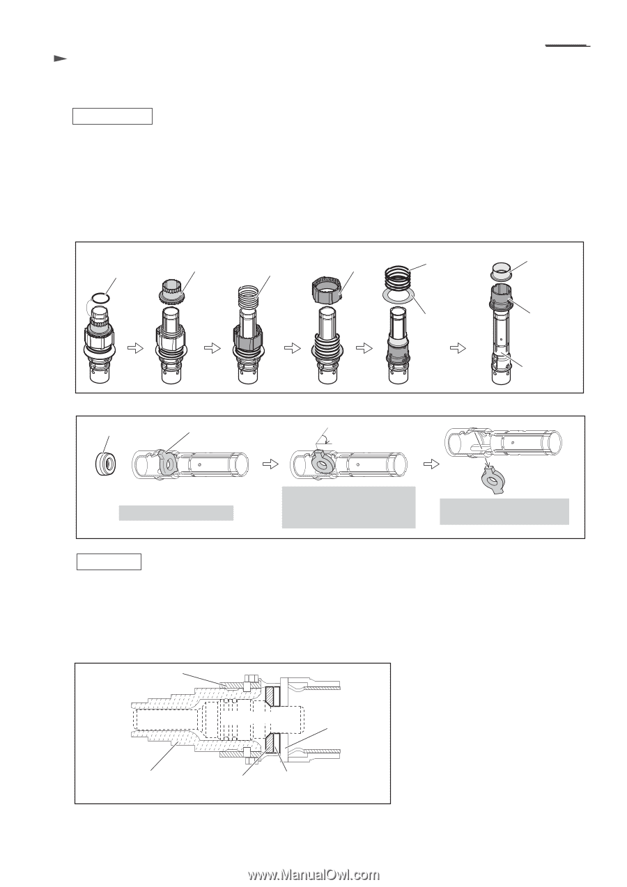
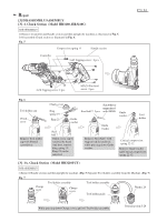
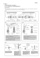
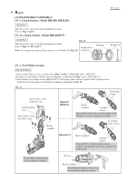
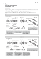
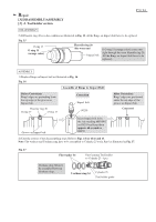
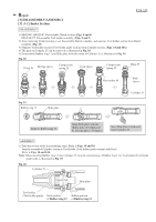
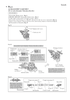
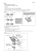
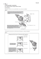
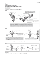
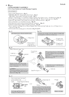
Repair [3] DISASSEMBLY/ASSEMBLY [3] -3. Cylinder Section P 10 / 24 DISASSEMBLY 1) HR3200C, HR3210C: Disassemble Chuck section. (Figs. 5 and 6) HR3210FCT: Disassemble Tool holder assembly. (Figs. 5 and 7) 2) After removing Crank housing cover, disassemble Barrel complete, and separate Tool holder section from Barrel complete. (Fig. 13) 3) Separate Tool holder section (Tool holder guide section) from Cylinder section. (Figs. 14 and 14A) 4) The parts on Cylinder 25 can be removed as illustrated in Fig. 18. 5) Disassemble Rubber ring 13 and Slide plate from the inside of Cylinder 25 as illustrated in Fig. 19. Fig. 18 O ring 26 Driving sleeve Compression spring 34 Lock sleeve Compression spring 42 Ring 29 Flat washer 40 Slide sleeve Fig. 19 Rubber ring 13 Slide plate Cylinder 25 Remove Rubber ring 13. Align Slide plate with the elliptic hole of Cylinder 25 by turning approx. 90 degree. Now Slide plate is removed from Cylinder 25. ASSEMBLY 1) Take the reverse of the disassembling steps. Refer to Figs. 19 and 18. Join the assembled Cylinder section to Tool holder (Tool holder guide section) with Pin 6. Refer to Figs. 14 and 14A. Note: When inserting Rubber ring 13 into Cylinder 25, face the steel portion of Rubber ring 13 to Tool holder (Tool holder guide) side as illustrated in Fig. 19. Fig. 20 Cylinder 25 Impact bolt Slide plate Tool holder (Tool holder guide) Steel portion of Rubber ring 13 Rubber portion of Rubber ring 13
-
 1
1 -
2
-
3
-
4
-
 5
5 -
 6
6 -
 7
7 -
 8
8 -
 9
9 -
 10
10 -
 11
11 -
 12
12 -
 13
13 -
 14
14 -
 15
15 -
16
-
17
-
18
-
19
-
20
-
21
-
22
-
23
-
24
 |
 |