Makita HR3210C Technical Reference - Page 14
Figs. 30 to 25., Fig. 30, Fig. 28, Fig. 29, Figs. 28 and 29., Cup washer 18
 |
View all Makita HR3210C manuals
Add to My Manuals
Save this manual to your list of manuals |
Page 14 highlights
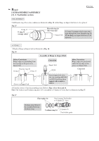
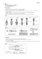
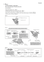
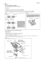
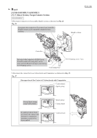
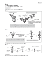
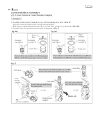
Repair [3] DISASSEMBLY/ASSEMBLY [3] -5. Motor Section, Torque Limiter Section DISASSEMBLY 6) Disassemble Armature as illustrated in Figs. 28 and 29. Fig. 28 5x25 Tapping screw: 4 pcs. Crank housing Torque limiter section may be left in Crank housing at this time. Torque limiter section Gear housing P 14 / 24 Motor housing Armature Use cloth to accept the grease from Gear room and to provent Torque limiter from having damage. Remove 5x25 Tapping screws. And separate Motor housing from Gear room. Do the disassemble work on the cloth to accept the grease from Gear housing and to provent Torque limiter from having damage. Fig. 29 Cup washer 18 Torque limiter section Note: Be careful not to lose Cup washer 18 for Crank shaft. Remove Torque limiter section by striking the Gear housing's edge with Plastic hammer, if Torque limiter section is left on the Gear housing. Handle of 1R045 1R346 Armature Remove Armature from Gear housing. 7) Torque limiter section can be disassembled as illustrated in Fig. 30. Fig. 30 1R269 Ring 10 Torque limiter complete Ball bearing 6001LLU Ball bearing 608DDW Key 4: 2 pcs. Spiral bevel gear 9 ASSEMBLY Take the reverse step of the disassembling procedure. Refer to Figs. 30 to 25.
-
 1
1 -
2
-
3
-
4
-
5
-
6
-
7
-
8
-
 9
9 -
 10
10 -
 11
11 -
 12
12 -
 13
13 -
 14
14 -
 15
15 -
 16
16 -
 17
17 -
 18
18 -
 19
19 -
20
-
21
-
22
-
23
-
24
 |
 |
