Makita HR3210C Technical Reference - Page 20
epair, 3] DISASSEMBLY/ASSEMBLY, 3] -7. Handle and Electrical Parts, 3] -8. Fastening Torque
 |
View all Makita HR3210C manuals
Add to My Manuals
Save this manual to your list of manuals |
Page 20 highlights
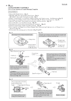
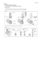
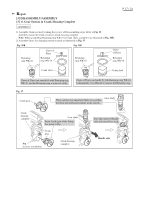
Repair [3] DISASSEMBLY/ASSEMBLY [3] -7. Handle Section and Electrical Parts ASSEMBLY Take the reverse of the disassembling steps. Note: Dust cover support and Dust cover are directional. Refer to Fig. 42. Fig. 42 Upper side Flat washer 5 Triangle mark of Dust cover support P 20 /24 5x40 Tapping screw: 2 pcs. Handle base Face the triangle mark of Dust cover support to the upper side and insert it to Dust cover. Bow portion of Dust cover Handle Face the bow portion of Dust cover to the upper side and assemble Dust cover to Handle. Lower side [3] DISASSEMBLY/ASSEMBLY [3] -8. Fastening Torque of Screw and Bolt Fasten Bolts and Drill chuck to the specific fastening torque. Refer to Fig. 43. Fig. 43 Item No. Description Q'ty Fastening Torque 18 M6 x 25 Hex socket head bolt 4 7.8 - 11.8 N.m 400 Drill chuck 1 34.3 - 44.1 N.m 18 Quick Change Drill Chuck (Standard Equipment for HR3210FCT) Barrel complete Crank Housing Complete 400 Chuck holder
-
 1
1 -
2
-
3
-
4
-
5
-
6
-
7
-
8
-
9
-
10
-
11
-
12
-
13
-
14
-
 15
15 -
 16
16 -
 17
17 -
 18
18 -
 19
19 -
 20
20 -
 21
21 -
 22
22 -
 23
23 -
 24
24
 |
 |
