Makita HR3210C Technical Reference - Page 5
] DISASSEMBLY/ASSEMBLY, 3] -1. Chuck Model HR3200, HR3210C, epair, 3] -1A. Chuck
 |
View all Makita HR3210C manuals
Add to My Manuals
Save this manual to your list of manuals |
Page 5 highlights
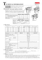
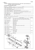
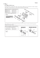
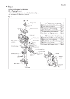
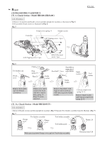
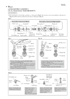
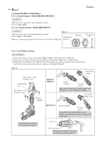
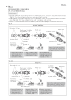
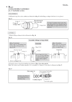
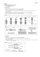
Repair [3] DISASSEMBLY/ASSEMBLY [3] -1. Chuck Section (Model HR3200, HR3210C) DISASSEMBLY 1) Remove Controller and Handle section and then upright the machine as illustrated in Fig. 5. 2) Disassemble Chuck section as illustrated in Fig. 6. Fig. 5 Compression spring 11 Handle section Controller 5x25 Tapping screw : 2 pcs. P 5 / 24 4x18 Tapping screw: 2 pcs. M5x20 Pan head screw: 2 pcs. Fig. 6 Tool holder cap Chuck cover Remove Tool holder cap with Slotted screwdriver. Chuck cover Ring spring 19 Ring 21 Guide washer Steel ball 7 Chuck cover can be removed by hand. And then, remove Ring spring 19. Ring 21 can be removed. Screwdriver magnetized Steel ball 7: 2 pcs. with 1R288 Guide washer Remove Steel ball 7 with magnetized Screwdriver, while pressing down Guide washer. Guide washer Tool holder Conical compression spring 22-32 Remove Guide washer and Conical compression spring 22-32. [3] -1A. Chuck Section (Model HR3210FCT) DISASSEMBLY 1) Remove Handle section and then upright the machine. (Fig. 5) Separate Tool holder assembly from the Machine. (Fig. 7) Fig. 7 Change cover Tool holder assembly Change cover Tool holder assembly Tool holder guide Washer 28 While pressing down Change cover, pull off Tool holder assembly. Retaining ring S-28
-
 1
1 -
 2
2 -
 3
3 -
 4
4 -
 5
5 -
 6
6 -
 7
7 -
 8
8 -
 9
9 -
 10
10 -
 11
11 -
12
-
13
-
14
-
15
-
16
-
17
-
18
-
19
-
20
-
21
-
22
-
23
-
24
 |
 |
