Makita HR3210C Technical Reference - Page 22
ircuit diagram, iring diagram, HR3200C, HR3210C, Handle, Motor housing, Handle base, Fig. D-1, Fig.
 |
View all Makita HR3210C manuals
Add to My Manuals
Save this manual to your list of manuals |
Page 22 highlights
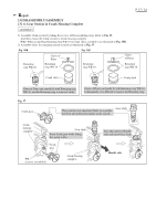
Circuit diagram HR3200C, HR3210C Fig. D-1 Color index of lead wires' sheathe Black White Red Switch * Lead wire (white ) of Power supply cord is blue for some countries. * Lead wire (black ) of Power supply cord is brown for some countries. P 22 / 24 Handle with Handle cover Handle base Motor housing Dial Controller T2 T1 Lead unit Power supply cord Connector of Lead unit Wiring diagram HR3200C, HR3210C Fig. D-2 Controller Motor housing Do not slack the lead wires in this area. Fix them with Lead wire holders and Ribs. Switch Handle Lead wire holder (A) Rib for Cotroller Dial (B) Rib of Motor housing Lead wire of Power supply cord Power supply cord Handle base Rib Cord guard Connector of Lead unit Do not put the lead wires of Power supply cord on the Ribs (A) and (B). Lead unit Route the lead wires of Lead unit through the opening of Handle base and Handle.
-
 1
1 -
2
-
3
-
4
-
5
-
6
-
7
-
8
-
9
-
10
-
11
-
12
-
13
-
14
-
15
-
16
-
 17
17 -
 18
18 -
 19
19 -
 20
20 -
 21
21 -
 22
22 -
 23
23 -
 24
24
 |
 |
