Makita HR3210C Technical Reference - Page 7
] DISASSEMBLY/ASSEMBLY, 3] -1. Chuck Model HR3200, HR3210C, epair, 3] -1A. Chuck
 |
View all Makita HR3210C manuals
Add to My Manuals
Save this manual to your list of manuals |
Page 7 highlights
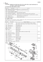
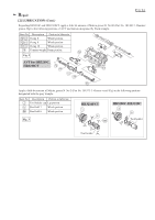
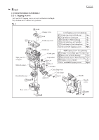
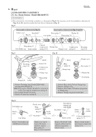
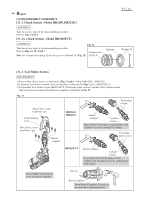
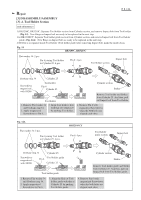
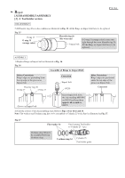
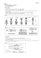
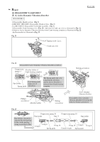
Repair [3] DISASSEMBLY/ASSEMBLY [3] -1. Chuck Section (Model HR3200, HR3210C) ASSEMBLY Take the reverse steps of the disassembling procedure. Refer to Figs. 6 and 5. [3] -1A. Chuck Section (Model HR3210FCT) ASSEMBLY Fig. 12 Take the reverse steps of the disassembling procedure. Refer to Figs. 11, 10, 9 and 7. Note: Fit Compression spring 42 into the groove of Washer 28. (Fig. 12) Compression spring 42 Groove P 7 / 24 Washer 28 [3] -2. Tool Holder Section DISASSEMBLY 1) Disassemble Chuck section as illustrated in Figs. 5 and 6. (Model HR3200C, HR3210C) 1A) Separate Tool holder assembly from the Machine as illustrated in Figs 5 and 7. (HR3210FCT) 2) Disassemble Tool holder section (HR3210FCT: Tool holder guide section) together with Cylinder section. And Oil seal can be removed from Barrel complete as illustrated in Fig. 13. Fig. 13 Tool holder section M4x16 Hex socket head bolt: 1 pc. Crank housing cover M6x25 Hex socket head bolt: 4 pcs. HR3200C HR3210C Barrel complete Barrel complete Cylinder section Disassemble Tool holder section together with Cylinder section by striking Tool holder. Tool holder guide section HR3210FCT Barrel complete Cylinder section Disassemble Tool holder guide section together with Cylinder section by striking Tool holder guide. Disassemble Crank housing cover and Barrel complete. Oil seal Barrel complete From Barrel Complete, Oil seal can be removed as illustrated above.
-
 1
1 -
 2
2 -
 3
3 -
 4
4 -
 5
5 -
 6
6 -
 7
7 -
 8
8 -
 9
9 -
 10
10 -
 11
11 -
 12
12 -
13
-
14
-
15
-
16
-
17
-
18
-
19
-
20
-
21
-
22
-
23
-
24
 |
 |
