Makita HR3210C Technical Reference - Page 17
] DISASSEMBLY/ASSEMBLY, 3] -6. Gear in Crank Housing Complete, epair
 |
View all Makita HR3210C manuals
Add to My Manuals
Save this manual to your list of manuals |
Page 17 highlights
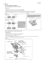
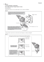
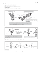
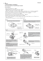
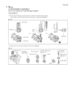
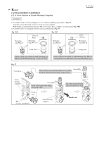
Repair [3] DISASSEMBLY/ASSEMBLY [3] -6. Gear Section in Crank Housing Complete P 17 / 24 ASSEMBLY 1) Assemble Crank section by taking the reverse of Disassembling steps. Refer to Fig. 3.5. And then, mount the Crank section to Crank housing complete. Note: When assembling Retaining ring WR-10 to Crank shaft, assemble it as illustrated in Fig. 36R. 2) Assemble Gears for changing operation mode as illustrated in Fig. 37. Fig. 36R Retaining ring WR-10 Claws of Pliers Retaining ring WR-10 Fig. 36F Retaining ring WR-10 Claws of Pliers Retaining ring WR-10 Crank shaft Crank shaft Claws of Pliers can exactly fit with Retaining ring WR-10, and the Retaining ring is removed easily. Claws of Pliers can hardly fit with Retaining ring WR-10. Consequently, it is difficult to remove the Retaining ring. Fig. 37 Crank gear Gear shaft These notches are important Marks to assemble the Gear unit in Rotary hammer mode exactly. Crank housing complete Gear shaft Insert Crank gear while fitting this notch to Pin. Crank gear Pin (factory assembled) Crank housing complete Face this notch to Handle side and insert Gear shaft. Handle side
-
 1
1 -
2
-
3
-
4
-
5
-
6
-
7
-
8
-
9
-
10
-
11
-
 12
12 -
 13
13 -
 14
14 -
 15
15 -
 16
16 -
 17
17 -
 18
18 -
 19
19 -
 20
20 -
 21
21 -
 22
22 -
23
-
24
 |
 |
