Makita HR3210C Technical Reference - Page 11
epair, 3] DISASSEMBLY/ASSEMBLY, 3] -4. Active Dynamic Vibration Absorber
 |
View all Makita HR3210C manuals
Add to My Manuals
Save this manual to your list of manuals |
Page 11 highlights
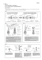
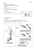
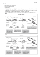
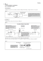
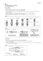
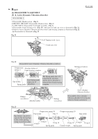
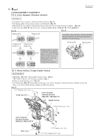
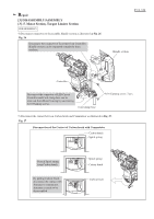
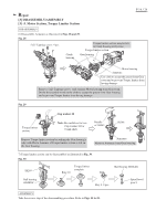
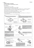
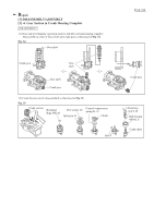
Repair [3] DISASSEMBLY/ASSEMBLY [3] -4. Active Dynamic Vibration Absorber DISASSEMBLY 1) Disassemble Handle section. (Fig. 5) 2) HR3200C, HR3210FC: Disassemble Chuck section. (Fig. 6) 2A) HR3210FCT: Disassemble Tool holder assembly. (Fig. 7) 3) Disassemble Crank housing cover. (Fig. 13) And remove Crank cap cover as illustrated in Fig. 21. 4) Remove Active Dynamic Vibration Absorber from Crank housing complete as illustrated in Fig. 22. And disassemble as illustrated in Fig. 23. Fig. 21 4x14 Tapping screw: 2 pcs. Crank cap cover P 11 / 24 Fig. 22 Disassemble Active Dynamic Vibration Absorber as follows. Compression Absorber holder of spring 11 Crank housing complete Slotted screwdriver Pipe holder Push Spring guide (inner part of Spring guide Absorber). The Spring guide tilts to be locked inside Absorber, and the end of Absorber is released from Crank housing complete. Phillips screwdriver Absorber holder Phillips screwdriver Active dynamic vibration absorber Disassemble Active dynamic vibration absorber by levering up with two Slotted screwdriver. Fig. 23 Pipe holders can now be separated by turning Pipe holders while pushing strong toward each other. Compression spring 10 Compression spring 10 Pipe holder Pipe 15 Pipe holder O ring 8 O ring 8 O ring 18 O ring 18 O ring 8 O ring 8 Spring guide Counter weight Spring guide
-
 1
1 -
2
-
3
-
4
-
5
-
 6
6 -
 7
7 -
 8
8 -
 9
9 -
 10
10 -
 11
11 -
 12
12 -
 13
13 -
 14
14 -
 15
15 -
 16
16 -
17
-
18
-
19
-
20
-
21
-
22
-
23
-
24
 |
 |
