Makita HR3210C Technical Reference - Page 18
Fig. 31A, Fig. 39, Fig. 40, Fig. 31
 |
View all Makita HR3210C manuals
Add to My Manuals
Save this manual to your list of manuals |
Page 18 highlights
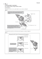
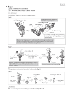
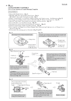
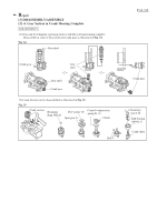
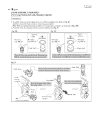
Repair [3] DISASSEMBLY/ASSEMBLY [3] -6. Gear Section in Crank Housing Complete P 18 / 24 ASSEMBLY 3) Assemble Spiral bevel gear 37, Link arm, Seal ring B and Link plate as illustrated in Fig. 39. 4) Assemble Crank cap as illustrated in Fig. 40. 5) Assemble Crank cap cover. The triangle mark on Change lever has to designate the mark of Rotary hammer mode on Crank cap cover as illustrated in Fig. 31. Fig. 39 Push Spiral bevel gear 37 into Crank housing complete until it stops. Push Link arm into Crank housing complete until the notches of Link arm come into sight in Crank housing complete. Assemble Link plate by fitting its bosses to the notches of Link arm. Spiral bevel gear 37 Notches of The notches of Link arm Link arm come into sight. Seal ring B Boss Link plate Fig. 40 Crank cap Link plate Assemble Crank cap to Crank housing complete while keeping Change lever in the position illustrated in Fig. 31A. Pin of Spur gear 33 complete which is mounted on the reverse side of Crank cap is fit into this hole. 6) Assemble the remaining parts by taking the reverse of the disassembling steps.
-
 1
1 -
2
-
3
-
4
-
5
-
6
-
7
-
8
-
9
-
10
-
11
-
12
-
 13
13 -
 14
14 -
 15
15 -
 16
16 -
 17
17 -
 18
18 -
 19
19 -
 20
20 -
 21
21 -
 22
22 -
 23
23 -
24
 |
 |
