Makita HR3210C Technical Reference - Page 19
] DISASSEMBLY/ASSEMBLY, 3] -7. Handle and Electrical Parts, epair, HR3200C, HR3210C,
 |
View all Makita HR3210C manuals
Add to My Manuals
Save this manual to your list of manuals |
Page 19 highlights
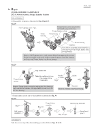
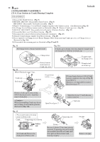
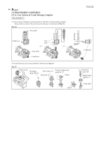
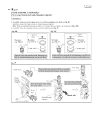
Repair P 19 / 24 [3] DISASSEMBLY/ASSEMBLY [3] -7. Handle Section and Electrical Parts DISASSEMBLY 1) Disassemble Handle section as illustrated in Fig. 25 and 26. 2) Controller and Power supply cord can be removed. (Fig. 26) 3) HR3200C: Disassemble Handle cover. ON-OFF Switch can be replaced as illustrated in Fig. 41. 3A) HR3210C or HR3210FCT: After removing ON-OFF Switch, Handle section can be disassembled as illustrated in Fig. 41A. Fig. 41 HR3200C Unscrew 4x18 Tapping screw. And separate Handle cover with Slotted screwdriver. Replace ON-OFF Switch etc. Switch lever Switch holder complete Handle Handle cover 4x18 Tapping screw : 1 pc. Handle ON-OFF Switch Lead unit Fig. 41A Unscrew 4x18 Tapping screw. And separate Handle cover with Slotted screwdriver. Handle cover 4x18 Tapping screw: 1 pc. HR3210C HR3210FCT Replace ON-OFF Switch etc. Handle Section can be disassembled as illustrated below. Switch holder Switch lever complete 5x40 Tapping Screw: 2 pcs. Flat washer 5: 2 pcs. Compression spring 11 Dust cover support Dust cover Lead unit ON-OFF Switch Handle base 5x25 Tapping screw: 2 pcs. Shoulder sleeve 6: 2 pcs. Handle
-
 1
1 -
2
-
3
-
4
-
5
-
6
-
7
-
8
-
9
-
10
-
11
-
12
-
13
-
 14
14 -
 15
15 -
 16
16 -
 17
17 -
 18
18 -
 19
19 -
 20
20 -
 21
21 -
 22
22 -
 23
23 -
 24
24
 |
 |
