Makita HR3210C Technical Reference - Page 12
] DISASSEMBLY/ASSEMBLY, 3] -4. Active Dynamic Vibration Absorber, epair, 3] -5. Motor
 |
View all Makita HR3210C manuals
Add to My Manuals
Save this manual to your list of manuals |
Page 12 highlights
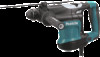
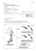
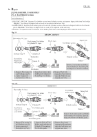
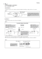
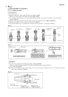
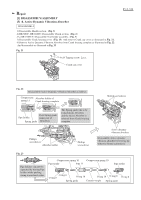
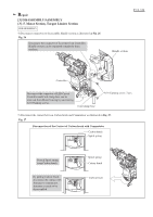
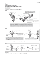
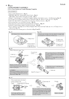
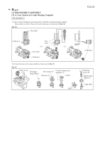
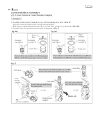
Repair [3] DISASSEMBLY/ASSEMBLY [3] -4. Active Dynamic Vibration Absorber P 12 / 24 ASSEMBLY 1) Assemble Active dynamic vibration absorber. Refer to Fig. 23. 2) Set Spring guide to the position in place as illustrated in Fig. 24. 3) Mount the Active dynamic vibration absorber on the both side of Crank housing complete. (Fig. 25) 4) After the step of Fig. 25, take the reverse of disassembling. Refer to Figs 21, 13, 7 or 6 and Fig. 5. Fig. 24 Fig. 25 Spring guide Spring guide Assemble Active dynamic vibration absorber by pressing while maintaining the position parallel to Crank housing. Compression Compression spring 10 spring 10 Spring guide Spring guide If Spring guide is locked in Absorber, push Spring guide so as not to be stuck and check that the tip of Spring guide comes out by return force of Compression spring 10. [3] -5. Motor Section, Torque Limiter Section DISASSEMBLY 1) HR3200C, HR3210C: Disassemble Chuck section. (Fig. 6). HR3210FCT: Remove Tool holder assembly. (Fig. 7) 2) Remove Crank housing cover. (Fig. 13) 3) As illustrated in Fig. 25, disassemble Crank cap cover, Active dymamic vibration absorber, Handl.e section and Rear cover from Crank housing complete and Motor housing. Fig. 25 4x14 Tapping screw: 2 pcs. Crank cap cover Active dymamic vibration absorber (HR3210C, HR3210FCT) Handle Section 5x20 Pan head screw: 2 pcs. Active dymamic vibration absorber (HR3210C, HR3210FCT) Rear cover 5x25 Tapping screw: 2 pcs. 4x18 Tapping screw: 2 pcs.
-
 1
1 -
2
-
3
-
4
-
5
-
6
-
 7
7 -
 8
8 -
 9
9 -
 10
10 -
 11
11 -
 12
12 -
 13
13 -
 14
14 -
 15
15 -
 16
16 -
 17
17 -
18
-
19
-
20
-
21
-
22
-
23
-
24
 |
 |