Makita HR3210C Technical Reference - Page 9
] DISASSEMBLY/ASSEMBLY, 3] -2. Tool holder epair
 |
View all Makita HR3210C manuals
Add to My Manuals
Save this manual to your list of manuals |
Page 9 highlights
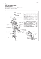
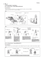
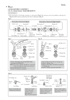
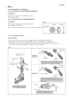
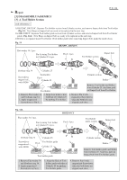
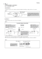
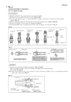
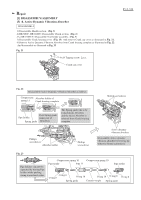
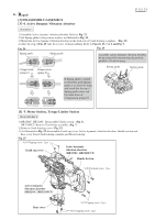
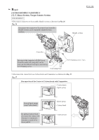
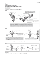
Repair [3] DISASSEMBLY/ASSEMBLY [3] -2. Tool holder section P 9 / 24 DISASSEMBLY 5) If Fluoride ring 20 is in the condition as illustrated in Fig. 15, all the Rings on Impact bolt have to be replaced. Fig. 15 O ring 15 O ring 15 (orange color) Fluoride ring 20 (the worn one) Impact bolt if O ring 15 (orange color) comes into sight through the worn Fluoride ring 20, All the Rings on Impact bolt have to be replaced, ASSEMBLY 1) Replace Rings on Impact bolt as illustrated in Fig. 16. Fig. 16 Assemble of Rings to Impact Bolt Before Correction: Rings' edges are protruding from the top edge of the groove on Impact bolt. Fluoride ring 20 O ring 15 O ring 15 Correction Impact bolt 1R259 After Correction: Rings' edges are positioned under the top edge of the groove on Impact bolt. Corrected Groove on Impact bolt Insert Impact bolt from the side marking HR3000C on 1R259 and keep them approx. 60 seconds in 1R259. 2) Take the reverse of the disassembling steps. Refer to Figs. 14 (or 14A) and 13. Note: Flat washers and Urethane ring have to be assembled to Cylinder 25 to fix Pin 6 as illustrated in Fig. 17. Fig. 17 Flat washer 34 Pin 6 joining Tool holder to Cylinder 25: 4 pcs. Urethane ring 34 has to be assembled between Urethane rings. Urethane ring 34 Cylinder 25 Tool holder guide
-
 1
1 -
2
-
3
-
 4
4 -
 5
5 -
 6
6 -
 7
7 -
 8
8 -
 9
9 -
 10
10 -
 11
11 -
 12
12 -
 13
13 -
 14
14 -
15
-
16
-
17
-
18
-
19
-
20
-
21
-
22
-
23
-
24
 |
 |
