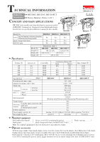
Makita HR3210C Technical Reference - Page 6
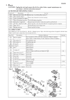
] DISASSEMBLY/ASSEMBLY, 3] -1A. Chuck Model HR3210FCT, epair
 |
View all Makita HR3210C manuals
Add to My Manuals
Save this manual to your list of manuals |
Page 6 highlights
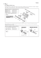
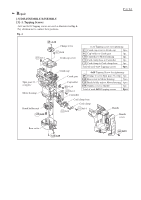
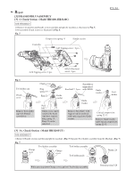
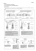
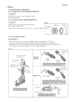
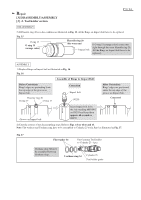
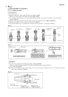
Repair P 6 /24 [3] DISASSEMBLY/ASSEMBLY [3] -1A. Chuck Section (Model HR3210FCT) DISASSEMBLY 2) The construction of Tool holder assembly is as illustrated in Fig. 8. The rear parts can be disassembled as illustrated in Figs. 9 and 10. And disassemble the front Parts as illustrated in Fig. 11. Fig. 8 Disassemble as illustrated in Fig. 11. Chuck cover Steel ball 7 Ring 21 Disassemble as illustrated in Figs. 9 and 10. Flat washer 37 Washer 28 Tool holder Ring spring 34 Ring spring 19 Tool holder cap Guide washer Conical compression Change ring Compression spring 22-32 Change cover spring 42 Retaining ring S-28 Fig. 9 Fig. 10 Retaining ring S-28 1R269 Washer 28 Compression spring 42 Change ring Tool Washer 28 holder Ring spring 34 1. Remove Retaining ring 28 with 1R269 while pressing down Washer 28. Note: Keep to press Washer 28 until it is removed so as not to be slung by Compression spring 42. 2. Disassemble Washer 28 slowly. 3. Remove Compression spring 42. 1R003 Ring spring 34 Change ring Change cover Flat washer 37 Change ring Tool holder Tool holder 1. Remove Ring spring 34 from Change ring. 2. Remove Change cover. 3. Remove Flat washer 37 from the rim portion of Change ring. 4. Remove Change ring from Tool holder. Fig. 11 Tool holder cap Chuck cover Tool holder Remove Tool holder cap with Slotted screwdriver. Chuck cover Ring spring 19 Ring 21 Steel ball 7 Guide washer Tool holder Chuck cover can be removed by hand. And then, remove Ring spring 19. Ring 21 can be removed. Screwdriver magnetized with 1R288 Steel Ball 7: 2 pcs. Guide washer Remove Steel ball 7 with magnetized Screwdriver while pressing down Guide washer. Guide washer Tool holder Conical compression spring 22-32 Remove Guide washer and Conical compression spring 22-32.
-
 1
1 -
 2
2 -
 3
3 -
 4
4 -
 5
5 -
 6
6 -
 7
7 -
 8
8 -
 9
9 -
 10
10 -
 11
11 -
 12
12 -
13
-
14
-
15
-
16
-
17
-
18
-
19
-
20
-
21
-
22
-
23
-
24
 |
 |
