Motorola 2700 User Manual - Page 11
Overview Of Powerline Mu - antenna
 |
View all Motorola 2700 manuals
Add to My Manuals
Save this manual to your list of manuals |
Page 11 highlights
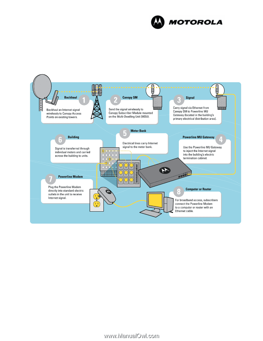
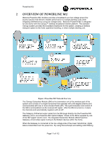
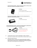
Powerline MU 2 OVERVIEW OF POWERLINE MU Motorola Powerline MU Solution provides a broadband over low-voltage power line access solution that delivers reliable performance to multiple-dwelling units while mitigating interference by using low voltage wires. Motorola Powerline MU is designed for and works with the Canopy™ wireless broadband Internet platform. The standard Canopy system provides the broadband backbone for the system, creating a wireless transport system to the hotel, apartment building, or other multiple dwelling unit. Figure 1 Powerline MU Network Overview The Canopy Subscriber Module (SM) is the termination unit of the wireless part of the system and consists of a single transceiver that operates with a 60-degree antenna and communicates with one or more Access Points (AP). The synchronization and control of the SM is accomplished via the received AP signal. After the SM is turned on, it scans the channels and automatically registers with an AP. The Category 5 Ethernet output cable from the SM plugs directly into the Powerline MU Gateway unit or via a Powerline MU Hybrid Adapter. Power to the SM is supplied by use of the SM "pigtail" electric cord. The integrated Subscriber Module (SM)-Powerline Gateway unit provides signal routing to the Modem devices within the home. When the Gateway is connected to the low voltage side of the power transformer, digital data is transmitted over the power line. By using this technique and adding notch filtering Page 11 of 112
-
 1
1 -
2
-
3
-
4
-
5
-
 6
6 -
 7
7 -
 8
8 -
 9
9 -
 10
10 -
 11
11 -
 12
12 -
 13
13 -
 14
14 -
 15
15 -
 16
16 -
17
-
18
-
19
-
20
-
21
-
22
-
23
-
24
-
25
-
26
-
27
-
28
-
29
-
30
-
31
-
32
-
33
-
34
-
35
-
36
-
37
-
38
-
39
-
40
-
41
-
42
-
43
-
44
-
45
-
46
-
47
-
48
-
49
-
50
-
51
-
52
-
53
-
54
-
55
-
56
-
57
-
58
-
59
-
60
-
61
-
62
-
63
-
64
-
65
-
66
-
67
-
68
-
69
-
70
-
71
-
72
-
73
-
74
-
75
-
76
-
77
-
78
-
79
-
80
-
81
-
82
-
83
-
84
-
85
-
86
-
87
-
88
-
89
-
90
-
91
-
92
-
93
-
94
-
95
-
96
-
97
-
98
-
99
-
100
-
101
-
102
-
103
-
104
-
105
-
106
-
107
-
108
-
109
-
110
-
111
-
112
 |
 |