Motorola 2700 User Manual - Page 26
Inductive Coupling Installation Diagram
 |
View all Motorola 2700 manuals
Add to My Manuals
Save this manual to your list of manuals |
Page 26 highlights
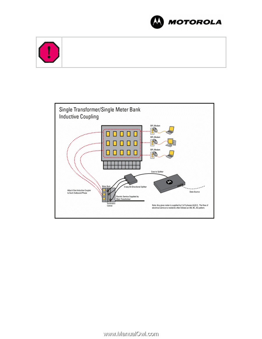
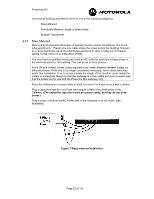
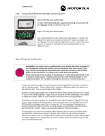
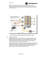
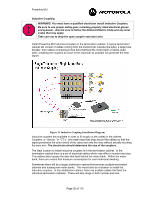
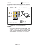
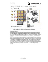
Powerline MU Inductive Coupling WARNING! You must have a qualified electrician install Inductive Couplers. Be sure to use proper safety gear, including properly rated electrical gloves and eyewear. Also be sure to follow the National Electric Code and any local codes that may apply. Take care not to drop the open coupler onto bare wire. Install Powerline MU Inductive Couplers in the termination cabinet. A typical termination cabinet will consist of cables coming from the transformer outside (line side), a large fuse breaker, then cables connecting to bus bars that feed the meter bank or banks (load side). Installing the couplers as close to the load side as possible will generate the best signal. Figure 11 Inductive Coupling Installation Diagram Inductive couplers are available in sizes to fit snugly on the cables in the cabinet. Couplers, or "donuts, "or "CT's," are metal rings that wrap around the cables so that the signal penetrates the outer shield of the cable and onto the lines without actually touching the bare wire The electrician should determine the size of the couplers. The ideal location to install inductive couplers is in the termination cabinet. In the termination cabinet there is a set of electrical cables which may differ in number and size. This cabinet also houses the bars that feed behind the meter bank. Within the meter bank, there are meters that measure consumption for each individual dwelling. Sometimes there will be a larger distribution cabinet that services multiple termination cabinets and subsequent meter banks. This would also be a location to install the inductive couplers. In this distribution cabinet, there are multiple cables that feed the individual termination cabinets. These will also range in both number and size. Page 26 of 112
-
 1
1 -
2
-
3
-
4
-
5
-
6
-
7
-
8
-
9
-
10
-
11
-
12
-
13
-
14
-
15
-
16
-
17
-
18
-
19
-
20
-
 21
21 -
 22
22 -
 23
23 -
 24
24 -
 25
25 -
 26
26 -
 27
27 -
 28
28 -
 29
29 -
 30
30 -
 31
31 -
32
-
33
-
34
-
35
-
36
-
37
-
38
-
39
-
40
-
41
-
42
-
43
-
44
-
45
-
46
-
47
-
48
-
49
-
50
-
51
-
52
-
53
-
54
-
55
-
56
-
57
-
58
-
59
-
60
-
61
-
62
-
63
-
64
-
65
-
66
-
67
-
68
-
69
-
70
-
71
-
72
-
73
-
74
-
75
-
76
-
77
-
78
-
79
-
80
-
81
-
82
-
83
-
84
-
85
-
86
-
87
-
88
-
89
-
90
-
91
-
92
-
93
-
94
-
95
-
96
-
97
-
98
-
99
-
100
-
101
-
102
-
103
-
104
-
105
-
106
-
107
-
108
-
109
-
110
-
111
-
112
 |
 |