Motorola 2700 User Manual - Page 47
Screen in the Gateway.Next, enter the Management VID VLAN ID for the Powerline
 |
View all Motorola 2700 manuals
Add to My Manuals
Save this manual to your list of manuals |
Page 47 highlights
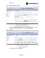
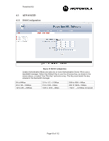
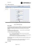
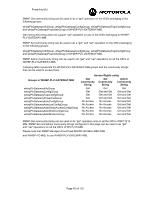
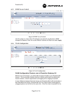
Powerline MU Gateway and Modem has been selected, care must be taken to ensure that the entire network has been properly configured to support VLAN functionality. There are two main ways that VLAN functionality can be implemented over Powerline. The first way assumes that the Modems are configured for NAT mode, and the second method assumes that the Modems are configured in Bridge mode. Figure 4 shows the test set up for both implementation examples. Figure 27 An Example Network Configuration for VLAN Implementation. VLAN Implementation using Modems in NAT Mode The following steps should be followed when operating Powerline MU in VLAN passthrough mode. The Powerline MU Gateway must be enabled for VLAN by checking the "VLAN Enable" box as shown in Figure 28. Figure 28 Example of VLAN Configuration Screen in the Gateway.Next, enter the Management VID (VLAN ID) for the Powerline network. Note: Powerline Management VID must be different from Canopy Management VID. After the Gateway has been configured for VLAN pass-through, the LAN and WAN ports will have different functionality. Where there was no differentiation between the LAN and WAN ports in standard operating mode, in VLAN mode, the LAN port will only accept VLAN tagged packets whereas the WAN port will only accept untagged packets. The WAN port can be used for: • Connecting a non-VLAN enabled Canopy network to the Gateway, thus allowing for a hybrid network where the Powerline network is VLAN enabled and the Canopy network is non-VLAN enabled. • Connecting to a PC or other non-VLAN IP device to the Powerline network. Page 47 of 112
-
 1
1 -
2
-
3
-
4
-
5
-
6
-
7
-
8
-
9
-
10
-
11
-
12
-
13
-
14
-
15
-
16
-
17
-
18
-
19
-
20
-
21
-
22
-
23
-
24
-
25
-
26
-
27
-
28
-
29
-
30
-
31
-
32
-
33
-
34
-
35
-
36
-
37
-
38
-
39
-
40
-
41
-
 42
42 -
 43
43 -
 44
44 -
 45
45 -
 46
46 -
 47
47 -
 48
48 -
 49
49 -
 50
50 -
 51
51 -
 52
52 -
53
-
54
-
55
-
56
-
57
-
58
-
59
-
60
-
61
-
62
-
63
-
64
-
65
-
66
-
67
-
68
-
69
-
70
-
71
-
72
-
73
-
74
-
75
-
76
-
77
-
78
-
79
-
80
-
81
-
82
-
83
-
84
-
85
-
86
-
87
-
88
-
89
-
90
-
91
-
92
-
93
-
94
-
95
-
96
-
97
-
98
-
99
-
100
-
101
-
102
-
103
-
104
-
105
-
106
-
107
-
108
-
109
-
110
-
111
-
112
 |
 |
