NEC NP-PA622U User's Manual - Page 21
Terminal Panel Features, BNC AUDIO IN Mini Jack Stereo Mini
 |
View all NEC NP-PA622U manuals
Add to My Manuals
Save this manual to your list of manuals |
Page 21 highlights
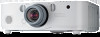
Terminal Panel Features 10 11 12 1 2 34 1. Introduction 89 7 13 14 5 6 15 16 1. HDMI 1 IN Connector (Type A) (→ page 126, 128, 132, 171) 2. HDMI 2 IN Connector (Type A) (→ page 126, 128, 132, 171) 3. DisplayPort IN Connector (→ page 126, 171) 4. BNC IN [R/Cr/CV, G/Y/Y, B/Cb/C, H, V] Connectors (BNC × 5) (→ page 125, 130) 5. BNC (CV) Input Connector (BNC × 1) (→ page 130) 6. BNC (Y/C) Input Connector (BNC × 2) (→ page 130) 7. BNC AUDIO IN Mini Jack (Stereo Mini) (→ page 128, 130) 8. COMPUTER IN/ Component Input Connector (Mini D-Sub 15 Pin) (→ page 13, 125) 9. COMPUTER AUDIO IN Mini Jack (Stereo Mini) (→ page 13, 125) 10. Ethernet/HDBase T Port (RJ-45) (→ page 133, 172) 11. USB-A Port (Type A) (→ page 172) (For future expansion. This port allows for power supply.) 12. HDMI OUT Connector (Type A) (→ page 129) 13. AUDIO OUT Mini Jack (Stereo Mini) (→ page 129) 14. 3D SYNC Connector (Mini DIN 4 Pin) (→ page 39) 15. PC CONTROL Port (D-Sub 9 Pin) (→ page 172) Use this port to connect a PC or control system. This enables you to control the projector using serial communication protocol. If you are writing your own program, typical PC control codes are on page 178. 16. REMOTE Connector (Stereo Mini) Use this connector for wired remote control of the projector using the NEC optional remote control. Connect the projector and optional remote control using a commercially available wired remote control cable. NOTE: • When a remote control cable is connected to the REMOTE connector, infrared remote control operations cannot be performed. • When [HDBaseT] is selected in the [REMOTE SENSOR] and the projector is connected to a commercially-available transmission device that supports HDBaseT, remote control operations in infra-red cannot be carried out if transmission of remote control signals has been set up in the transmission device. However, remote control using infrared rays can be carried out when the power supply of the transmission device is switched off. 8
-
 1
1 -
2
-
3
-
4
-
5
-
6
-
7
-
8
-
9
-
10
-
11
-
12
-
13
-
14
-
15
-
 16
16 -
 17
17 -
 18
18 -
 19
19 -
 20
20 -
 21
21 -
 22
22 -
 23
23 -
 24
24 -
 25
25 -
 26
26 -
27
-
28
-
29
-
30
-
31
-
32
-
33
-
34
-
35
-
36
-
37
-
38
-
39
-
40
-
41
-
42
-
43
-
44
-
45
-
46
-
47
-
48
-
49
-
50
-
51
-
52
-
53
-
54
-
55
-
56
-
57
-
58
-
59
-
60
-
61
-
62
-
63
-
64
-
65
-
66
-
67
-
68
-
69
-
70
-
71
-
72
-
73
-
74
-
75
-
76
-
77
-
78
-
79
-
80
-
81
-
82
-
83
-
84
-
85
-
86
-
87
-
88
-
89
-
90
-
91
-
92
-
93
-
94
-
95
-
96
-
97
-
98
-
99
-
100
-
101
-
102
-
103
-
104
-
105
-
106
-
107
-
108
-
109
-
110
-
111
-
112
-
113
-
114
-
115
-
116
-
117
-
118
-
119
-
120
-
121
-
122
-
123
-
124
-
125
-
126
-
127
-
128
-
129
-
130
-
131
-
132
-
133
-
134
-
135
-
136
-
137
-
138
-
139
-
140
-
141
-
142
-
143
-
144
-
145
-
146
-
147
-
148
-
149
-
150
-
151
-
152
-
153
-
154
-
155
-
156
-
157
-
158
-
159
-
160
-
161
-
162
-
163
-
164
-
165
-
166
-
167
-
168
-
169
-
170
-
171
-
172
-
173
-
174
-
175
-
176
-
177
-
178
-
179
-
180
-
181
-
182
-
183
-
184
-
185
-
186
-
187
-
188
-
189
-
190
-
191
-
192
-
193
-
194
 |
 |
