NEC NP-PA622U User's Manual - Page 9
Example 3 - In the case of portrait projection., Example 2 - If there is a wall behind the projector.
 |
View all NEC NP-PA622U manuals
Add to My Manuals
Save this manual to your list of manuals |
Page 9 highlights
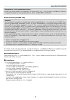
Important Information Clearance for Installing the Projector Allow ample clearance between the projector and its surroundings as shown below. The high temperature exhaust coming out of the device may be sucked into the device again. Avoid installing the projector in a place where air movement from the HVAC is directed at the projector. Heated air from the HVAC can be taken in by the projector's intake vent. If this happens, the temperature inside the projector will rise too high causing the over-temperature protector to automatically turn off the projectors power. Example 1 - If there are walls on both sides of the projector. 20 cm/7.9" or greater 13 cm/5.1" or greater Lamp cover Filter cover (Ventilation (inlet)) NOTE: The drawing shows the proper clearance required for the front, back and top of the projector. Example 2 - If there is a wall behind the projector. 10 cm/3.9" or greater Ventilation (outlet) NOTE: The drawing shows the proper clearance required for the back, sides and top of the projector. Example 3 - In the case of portrait projection. Filter cover (Ventilation (inlet)) 13 cm/5.1" or greater NOTE: • The drawing shows the proper clearance required for the front, back and top of the projector. • See page 134 for an installation example on portrait projection. vii
-
 1
1 -
2
-
3
-
 4
4 -
 5
5 -
 6
6 -
 7
7 -
 8
8 -
 9
9 -
 10
10 -
 11
11 -
 12
12 -
 13
13 -
 14
14 -
15
-
16
-
17
-
18
-
19
-
20
-
21
-
22
-
23
-
24
-
25
-
26
-
27
-
28
-
29
-
30
-
31
-
32
-
33
-
34
-
35
-
36
-
37
-
38
-
39
-
40
-
41
-
42
-
43
-
44
-
45
-
46
-
47
-
48
-
49
-
50
-
51
-
52
-
53
-
54
-
55
-
56
-
57
-
58
-
59
-
60
-
61
-
62
-
63
-
64
-
65
-
66
-
67
-
68
-
69
-
70
-
71
-
72
-
73
-
74
-
75
-
76
-
77
-
78
-
79
-
80
-
81
-
82
-
83
-
84
-
85
-
86
-
87
-
88
-
89
-
90
-
91
-
92
-
93
-
94
-
95
-
96
-
97
-
98
-
99
-
100
-
101
-
102
-
103
-
104
-
105
-
106
-
107
-
108
-
109
-
110
-
111
-
112
-
113
-
114
-
115
-
116
-
117
-
118
-
119
-
120
-
121
-
122
-
123
-
124
-
125
-
126
-
127
-
128
-
129
-
130
-
131
-
132
-
133
-
134
-
135
-
136
-
137
-
138
-
139
-
140
-
141
-
142
-
143
-
144
-
145
-
146
-
147
-
148
-
149
-
150
-
151
-
152
-
153
-
154
-
155
-
156
-
157
-
158
-
159
-
160
-
161
-
162
-
163
-
164
-
165
-
166
-
167
-
168
-
169
-
170
-
171
-
172
-
173
-
174
-
175
-
176
-
177
-
178
-
179
-
180
-
181
-
182
-
183
-
184
-
185
-
186
-
187
-
188
-
189
-
190
-
191
-
192
-
193
-
194
 |
 |
