Netgear GS418TPP Hardware Installation Guide - Page 10
Hardware Description, Front Panel, Back Panel, Hardware Overview
 |
View all Netgear GS418TPP manuals
Add to My Manuals
Save this manual to your list of manuals |
Page 10 highlights
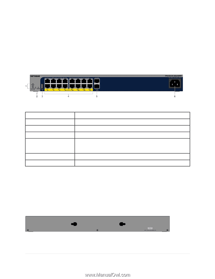
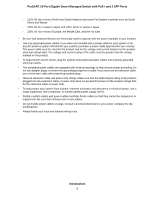
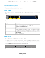
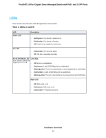
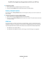
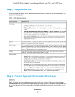
ProSAFE 16-Port Gigabit Smart Managed Switch with PoE+ and 2 SFP Ports Hardware Description This section describes the switch hardware features. Front Panel The switch provides sixteen 10/100/1000M BASE-T RJ-45 PoE ports. The following figure shows the front panel. Figure 1. Front panel Number 1 2 3 4 5 6 Description Power, Fan, and PoE LEDs (see LEDs on page 11). Reset and Factory Defaults buttons USB port Sixteen independent 10/100/1000M BASE-T RJ-45 PoE ports, each with a right LED that indicates the PoE status and a left LED that functions as the combined speed and activity LED (see LEDs on page 11). Two SFP ports One AC power receptacle Back Panel The switch integrates a fixed, internal power supply unit (PSU). The back panel does not contain any components other than two mounting holes that allow you to mount the switch horizontally or vertically and a serial console port for debugging. The bottom panel also contains mounting holes. For more information, see Step 4: Install the Switch on page 17. The following figure illustrates the back panel with the mounting holes. Figure 2. Back panel Hardware Overview 10
-
 1
1 -
2
-
3
-
4
-
 5
5 -
 6
6 -
 7
7 -
 8
8 -
 9
9 -
 10
10 -
 11
11 -
 12
12 -
 13
13 -
 14
14 -
 15
15 -
16
-
17
-
18
-
19
-
20
-
21
-
22
-
23
-
24
-
25
-
26
-
27
-
28
-
29
-
30
 |
 |