Netgear GS418TPP Hardware Installation Guide - Page 15
Step 1: Prepare the site, Step 2: Protect Against Electrostatic Discharge, Table 2. Site Requirements
 |
View all Netgear GS418TPP manuals
Add to My Manuals
Save this manual to your list of manuals |
Page 15 highlights
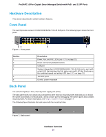
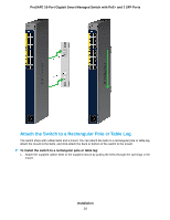
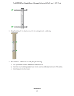
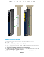
ProSAFE 16-Port Gigabit Smart Managed Switch with PoE+ and 2 SFP Ports Step 1: Prepare the Site Before you install the switch, ensure that the operating environment meets the site requirements that are listed in the following table. Table 2. Site Requirements Characteristics Mounting Access Power source Cabling Environmental Requirements • Desktop installations. Provide a flat table or shelf surface. • Wall installations. Use a mount that is supplied with the switch to attach the switch to a wall. • Attached to a rectangular table leg or pole with a secure locking tab. Use a mount with rubber belts, all of which are supplied with the switch, to attach the switch almost anywhere, such as a table leg or rectangular pole. • Rack-mount installations. Use a 19 inch (48.3 centimeter) EIA standard equipment rack that is grounded and physically secure. You also need the rack-mount kit that is supplied with the switch. Locate the switch in a position that allows you to access the front panel ports, view the front panel LEDs, and access the power connector. Use the AC power cord that is supplied with the switch. Make sure that the AC outlet is not controlled by a wall switch, which can accidentally turn off power to the outlet and the switch. Power supply cord must not be attached to the building surface, nor run through walls, ceilings, floors and similar openings in the building structure. Route cables to avoid sources of electrical noise such as radio transmitters, broadcast amplifiers, power lines, and fluorescent lighting fixtures. • Temperature. Install the switch in a dry area with an ambient temperature between 0ºC and 50ºC (32ºF and 122ºF). Keep the switch away from heat sources such as direct sunlight, warm-air exhausts, hot-air vents, and heaters. • Operating humidity. The maximum relative humidity of the installation location must not exceed 90%, noncondensing. • Ventilation. Do not restrict airflow by covering or obstructing air inlets on the sides of the switch. Keep at least 2 inches (5.08 centimeters) free on all sides for cooling. The room or wiring closet in which you install the switch must provide adequate airflow. • Operating conditions. Keep the switch at least 6 feet (1.83 meters) away from the nearest source of electromagnetic noise, such as a photocopy machine. Step 2: Protect Against Electrostatic Discharge WARNING: Static electricity can harm delicate components inside your system. To prevent static damage, discharge static electricity from your body before you touch any of the electronic components, such as the microprocessor. You can do so by periodically touching an unpainted metal surface on the switch. Installation 15
-
 1
1 -
2
-
3
-
4
-
5
-
6
-
7
-
8
-
9
-
 10
10 -
 11
11 -
 12
12 -
 13
13 -
 14
14 -
 15
15 -
 16
16 -
 17
17 -
 18
18 -
 19
19 -
 20
20 -
21
-
22
-
23
-
24
-
25
-
26
-
27
-
28
-
29
-
30
 |
 |