Netgear GS418TPP Hardware Installation Guide - Page 23
Step 8: Apply AC Power and Check the LEDs, Step 9: Manage the Switch, To apply AC power, Installation
 |
View all Netgear GS418TPP manuals
Add to My Manuals
Save this manual to your list of manuals |
Page 23 highlights
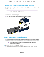
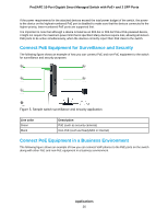
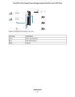
ProSAFE 16-Port Gigabit Smart Managed Switch with PoE+ and 2 SFP Ports Step 8: Apply AC Power and Check the LEDs The switch does not provide an on/off switch. The power cord connection controls the power. Before connecting the power cord, select an AC outlet that is not controlled by a wall switch, which can turn off power to the switch. To apply AC power: 1. Connect the end of the power cord to the AC power receptacle on the front of the switch. 2. Plug the AC power cord into a power source such as a wall socket or power strip. When you apply power, the Power LED on the switch front panel lights. if the Power LED does not light, check that the power cord is plugged in correctly and that the power source is good. Step 9: Manage the Switch The switch contains built-in web browser accessible software for viewing, changing, and monitoring the way it functions. This management software is not required for the switch to work. You can use the ports without using the management software. However, the management software enables the setup of VLAN and trunking features and also improves the efficiency of the switch, which results in the improvement of its overall performance as well as the performance of the network. After you power up the switch for the first time, you can configure the smart managed switch using the web browser-based management interface for advanced setup and configuration of features, or the Smart Control Center program (which requires a Windows computer) for very basic setup. For more information about managing the switch, see the installation guide on the resource CD and the user manual that you can download from downloadcenter.netgear.com. Note The switch's default IP address is 192.168.0.239 and its default subnet mask is 255.255.255.0. Installation 23
-
 1
1 -
2
-
3
-
4
-
5
-
6
-
7
-
8
-
9
-
10
-
11
-
12
-
13
-
14
-
15
-
16
-
17
-
 18
18 -
 19
19 -
 20
20 -
 21
21 -
 22
22 -
 23
23 -
 24
24 -
 25
25 -
 26
26 -
 27
27 -
 28
28 -
29
-
30
 |
 |