Netgear GS418TPP Hardware Installation Guide - Page 12
Switch Hardware Interfaces, RJ-45 Ports for 10/100/1000M BASE-T Connectivity, Reset Button
 |
View all Netgear GS418TPP manuals
Add to My Manuals
Save this manual to your list of manuals |
Page 12 highlights
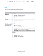
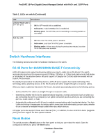
ProSAFE 16-Port Gigabit Smart Managed Switch with PoE+ and 2 SFP Ports Table 1. LEDs on switch (Continued) LED Description Link/ACT Mode LED for SFP fiber ports • • • Off: No SFP module link is established. Solid green. A valid 1000Mbps link is established. Blinking green. The SFP fiber port is transmitting or receiving packets at 1000 Mbps. PoE Max LED • Off. More than 7W of PoE power is available. • Solid amber. Less than 7W of PoE power is available. • Blinking amber. At least once during the previous two minutes, less than 7W of PoE power was available. Switch Hardware Interfaces The following sections describe the hardware interfaces on the switch. RJ-45 Ports for 10/100/1000M BASE-T Connectivity All RJ-45 copper ports support autosensing. When you insert a cable into an RJ-45 port, the switch automatically ascertains the maximum speed (10 Mbps, 100 Mbps, or 1 Gbps) and duplex mode (half-duplex or full-duplex) of the attached device. All ports support a Category 5e (Cat 5e) cable terminated with an 8-pin RJ-45 connector. To simplify the procedure for attaching devices, all RJ-45 ports support Auto Uplink technology. This technology allows attaching devices to the RJ-45 ports with either straight-through or crossover cables. When you insert a cable into the switch's RJ-45 port, the switch automatically performs the following actions: • Senses whether the cable is a straight-through or crossover cable. • Determines whether the link to the attached device requires a normal connection (such as when you are connecting the port to a computer) or an uplink connection (such as when you are connecting the port to a router, switch, or hub). • Automatically configures the RJ-45 port to enable communications with the attached device. The Auto Uplink technology compensates for setting uplink connections while eliminating concern about whether to use crossover or straight-through cables when you attach devices. All copper ports also support Power over Ethernet (PoE+). In addition, the two small form-factor pluggable (SFP) ports can support 1G fiber optical modules. Reset Button The switch provides a Reset button on the front panel so that you can reboot the switch. Save the configuration before you press the Reset button. Hardware Overview 12
-
 1
1 -
2
-
3
-
4
-
5
-
6
-
 7
7 -
 8
8 -
 9
9 -
 10
10 -
 11
11 -
 12
12 -
 13
13 -
 14
14 -
 15
15 -
 16
16 -
 17
17 -
18
-
19
-
20
-
21
-
22
-
23
-
24
-
25
-
26
-
27
-
28
-
29
-
30
 |
 |