Netgear GS418TPP Hardware Installation Guide - Page 22
Optional Step 6: Install SFP Transceiver Modules, Step 7: Connect Devices to the Switch
 |
View all Netgear GS418TPP manuals
Add to My Manuals
Save this manual to your list of manuals |
Page 22 highlights
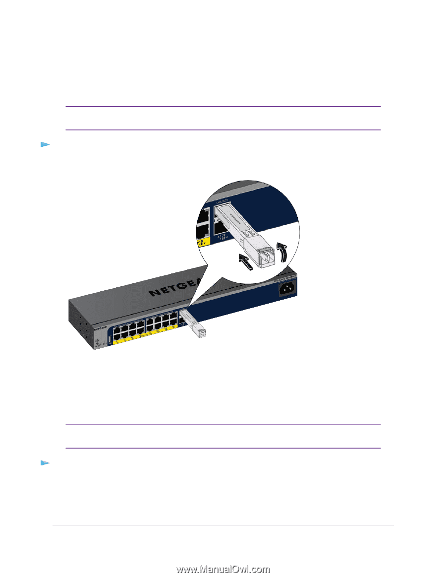
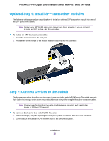
ProSAFE 16-Port Gigabit Smart Managed Switch with PoE+ and 2 SFP Ports Optional Step 6: Install SFP Transceiver Modules The following optional procedure describes how to install an optional SFP transceiver module into one of the SFP ports of the switch. Note Contact your NETGEAR sales office to purchase these modules. If you do not want to install an SFP module, skip this procedure. To install an SFP transceiver module: 1. Insert the transceiver into the SFP port. 2. Press firmly on the flange of the module to seat it securely into the connector. Step 7: Connect Devices to the Switch The following procedure describes how to connect computers to the switch's RJ-45 ports.The switch supports Auto Uplink technology, which allows you to attach devices using either straight-through or crossover cables. Note Ethernet specifications limit the cable length between the switch and the attached device to 328 feet (100 meters). To connect devices to the switch's RJ-45 ports: 1. Select a Category 5e (Cat 5e) or higher rated (Cat 6) cable terminated with an RJ-45 connector. 2. Connect each device to an RJ-45 network port on the switch front panel. Installation 22
-
 1
1 -
2
-
3
-
4
-
5
-
6
-
7
-
8
-
9
-
10
-
11
-
12
-
13
-
14
-
15
-
16
-
 17
17 -
 18
18 -
 19
19 -
 20
20 -
 21
21 -
 22
22 -
 23
23 -
 24
24 -
 25
25 -
 26
26 -
 27
27 -
28
-
29
-
30
 |
 |