Onkyo PR-SC5508 Owner Manual - Page 79
Using the 12V Triggers, to select 12V Trigger A, B or C Setup
 |
View all Onkyo PR-SC5508 manuals
Add to My Manuals
Save this manual to your list of manuals |
Page 79 highlights
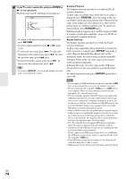
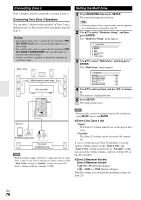
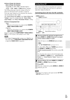
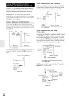
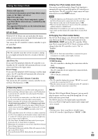
Using the 12V Triggers The 12V triggers A, B, and C can be used to turn on 12V trigger-capable components automatically when they are selected as the input source. The triggers can be set so that they activate when a connected component is selected as the input source for the main room, Zone 2, Zone 3 or any combination of rooms. When triggered, the output from a 12V TRIGGER OUT goes high (+12 volts and 150 milliamperes max. at TRIGGER OUT A; +12 volts and 25 milliamperes max. at TRIGGER OUT B and C). Hookup • Use a miniplug cable to connect the AV controller's 12V TRIGGER OUT A, B, or C jack to the 12 V trigger input on a connected component. When several components are turned on simultaneously by using triggers A, B, and C, depending on the type of components, a large amount of current may be drawn momentarily. To prevent this, you can delay trigger signals A, B, and C individually. Another application for trigger delay is eliminating the "thump" noise that's sometimes heard when a source component is turned on. Delaying the trigger signal for your power amplifier so that it's the last component to be turned on will accomplish this. 1 Press RECEIVER followed by SETUP. The main menu appears on screen. If the main menu doesn't appear, make sure the appropriate external input is selected on your TV. 2 Use R/X to select "Miscellaneous", and then press ENTER. The "Miscellaneous" menu appears. 3 Use R/X to select "12V Trigger A, B or C Setup", and then press ENTER. The "12V Trigger A, B or C Setup" screen appears. 6-3. 12V Trigger A Setup Delay 0sec BD/DVD Main VCR/DVR Main CBL/SAT Main GAME Main PC Main AUX Main 4 Use R/X to select "Delay", and use F/S to select: `0sec (Trigger A: default), 1sec (Trigger B: default), 2sec (Trigger C: default), or 3sec. When "0sec" is selected, the trigger signal is output as soon as the input source is changed. 5 Use R/X to select an input source, and use F/S to select an option. ` Off: No trigger signal is output. A 12-volt trigger signal is output when the connected component is selected as the source for: `Main (Trigger A: default): Main room. `Zone 2 (Trigger C: default): Zone 2. `Main/Zone 2: Main room or Zone 2. `Zone 3: Zone 3. `Main/Zone 3: Main room or Zone 3. `Zone 2/Zone 3: Zone 2 or Zone 3. `Main/Zone 2/Zone 3 (Trigger B: default): Main room, Zone 2, or Zone 3. 6 When you've finished, press SETUP. The setup menu closes. En 79
-
 1
1 -
2
-
3
-
4
-
5
-
6
-
7
-
8
-
9
-
10
-
11
-
12
-
13
-
14
-
15
-
16
-
17
-
18
-
19
-
20
-
21
-
22
-
23
-
24
-
25
-
26
-
27
-
28
-
29
-
30
-
31
-
32
-
33
-
34
-
35
-
36
-
37
-
38
-
39
-
40
-
41
-
42
-
43
-
44
-
45
-
46
-
47
-
48
-
49
-
50
-
51
-
52
-
53
-
54
-
55
-
56
-
57
-
58
-
59
-
60
-
61
-
62
-
63
-
64
-
65
-
66
-
67
-
68
-
69
-
70
-
71
-
72
-
73
-
 74
74 -
 75
75 -
 76
76 -
 77
77 -
 78
78 -
 79
79 -
 80
80 -
 81
81 -
 82
82 -
 83
83 -
 84
84 -
85
-
86
-
87
-
88
-
89
-
90
-
91
-
92
-
93
-
94
-
95
-
96
-
97
-
98
-
99
-
100
-
101
-
102
-
103
-
104
-
105
-
106
-
107
-
108
 |
 |
