Panasonic AJ-HDX900 Dvcpro Hd Camera - Page 16
continued - reviews
 |
UPC - 791871302781
View all Panasonic AJ-HDX900 manuals
Add to My Manuals
Save this manual to your list of manuals |
Page 16 highlights
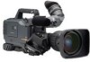
Chapter 2 Parts and their functions (continued) = VIDEO OUT OUTPUT SEL (output signal selection) switch This is used to select the signals output from the VIDEO OUT connector. VTR : In the recording or other EE mode, the camera images are output from the connectors; in the playback mode, it is the VTR's playback signals which are output. CAM : The camera images are output at all times. Furthermore, the audio output signals are synchronized with the video signals as well. For details on the video output, refer to "4-8-1 Settings of signals output from VIDEO OUT connector." > VIDEO OUT CHARACTER switch This is used to control the superimposing of the characters onto the images which are output from the VIDEO OUT connector. ON : The characters are superimposed onto the images. OFF : The characters are not superimposed onto the images. For details on the character types, refer to "4-8-1 Settings of signals output from VIDEO OUT connector." ? VIDEO OUT (signal switching) switch This switch switches the modes of output signals from the VIDEO OUT connector. HD SDI: To output HD SDI signals SD SDI: To output the down-converted SD SDI signals VBS: To output the down-converted composite video signals @ VIDEO OUT connector This is an output connector for video signals. Video signals linked to the setting of the VIDEO OUT switch (=, >, ?) are output from here. A REMOTE (remote control) connector The AJ-RC10G remote control unit (optional accessory) is connected here. B MON OUT (Monitor) connector This is the connector for outputting the video signal which is used for monitoring. HD SDI signals or analog HD Y signals are output from here. Whether characters are to be superimposed onto the images output from the VIDEO OUT connector can be selected separately using the internal menu. For details, refer to "4-8-2 Settings for signals output from the MON OUT connector." C GENLOCK IN connector The HD Y reference signal is supplied to this connector when the camera unit is to be gen-locked or the time code is to be externally locked. Composite video signals may be input as the reference signal instead but, in this case, the H phase cannot be adjusted. Also, it is not possible to externally lock the sub carrier of the unit's down-converter output (composite video signal). O Returned video images can be confirmed in the viewfinder screen by entering HD-Y signals. D EJECT button This is pressed to insert or eject the cassette. E STOP button This is pressed to stop the tape travel. F PLAY/PAUSE button This is pressed to view the playback picture on the viewfinder screen or using a color video monitor. The button's lamp comes on during playback. When it is pressed during playback, the unit is set to pause in the playback mode (PLAY PAUSE), and the button's lamp flashes. If the unit is left in the pause mode for two minutes, it automatically changes to the stop (STOP) mode. G REW (rewind) button and lamp When this button is pressed during stop, the tape is reviewed at high speed. Its lamp lights at this time. When it is pressed during playback or pause, the tape is reviewed at approximately 4 times the normal tape speed. Both the PLAY lamp and REW lamp light at this time. During the jump operation, the REW lamp flashes. H FF (fast forward) button and lamp When this button is pressed during stop, the tape is cued at high speed. Its lamp lights at this time. When it is pressed during playback or pause, the tape is cued at approximately 4 times the normal tape speed. Both the PLAY lamp and FF lamp light at this time. I EMERGENCY screw (inside rubber cap) If the cassette does not eject even when the EJECT button is pressed, use a screwdriver or similar implement to push and turn the EMERGENCY screw at the same time: this will cause the cassette to be ejected. For details, refer to "6-3-3 Emergency eject." 16
-
 1
1 -
2
-
3
-
4
-
5
-
6
-
7
-
8
-
9
-
10
-
 11
11 -
 12
12 -
 13
13 -
 14
14 -
 15
15 -
 16
16 -
 17
17 -
 18
18 -
 19
19 -
 20
20 -
 21
21 -
22
-
23
-
24
-
25
-
26
-
27
-
28
-
29
-
30
-
31
-
32
-
33
-
34
-
35
-
36
-
37
-
38
-
39
-
40
-
41
-
42
-
43
-
44
-
45
-
46
-
47
-
48
-
49
-
50
-
51
-
52
-
53
-
54
-
55
-
56
-
57
-
58
-
59
-
60
-
61
-
62
-
63
-
64
-
65
-
66
-
67
-
68
-
69
-
70
-
71
-
72
-
73
-
74
-
75
-
76
-
77
-
78
-
79
-
80
-
81
-
82
-
83
-
84
-
85
-
86
-
87
-
88
-
89
-
90
-
91
-
92
-
93
-
94
-
95
-
96
-
97
-
98
-
99
-
100
-
101
-
102
-
103
-
104
-
105
-
106
-
107
-
108
-
109
-
110
-
111
-
112
-
113
-
114
-
115
-
116
-
117
-
118
-
119
-
120
-
121
-
122
-
123
-
124
-
125
-
126
-
127
-
128
-
129
-
130
-
131
-
132
-
133
-
134
 |
 |
