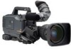
Panasonic AJ-HDX900 Dvcpro Hd Camera - Page 8
Features of the VTR unit, 3 Features of the Input/Output unit - hd
 |
UPC - 791871302781
View all Panasonic AJ-HDX900 manuals
Add to My Manuals
Save this manual to your list of manuals |
Page 8 highlights
Chapter 1 General (continued) 1-2 Features of the VTR unit O DVCPRO HD EX format system The VTR unit employs the DVCPRO HD EX recording format. Using the latest compression technology, it achieves two times the economy of the conventional DVCPRO HD format. O PRE RECORDING function provided as a standard configuration The VTR unit employs the PRE RECORDING function as the standard configuration. Pictures and voices of up to 7 seconds prior to pressing the VTR REC button can be recorded. (Refer to page 26) O Interval REC function and ONE-SHOT Recording function provided as a standard configuration The VTR unit employs the Interval REC function and the ONE-SHOT Recording function as the standard configuration. With memory control, this unit makes it possible to record in intervals with a minimum recording time in increments of one frame. This is particularly useful for shooting science and nature programs. Furthermore, when the unit is used for one-shot recording, frame-by-frame shooting is easily accomplished. (Refer to page 27) O Valid frame information The VTR unit supports multiple formats. For low frame rates, valid frame information is recorded in the user bits etc. When HD SDI signals are output, valid frame information is also output. (Refer to page 39) O Input signals from four separate audio channels The unit enables audio input signals from four channels to be selected separately. Further, the level of the signal in each channel can be monitored on the LCD display window. (Refer to page 12) O Built-in DOLBY NR The CUE audio recording circuitry contains a DOLBY B noise reduction circuit. O Unislot wireless receiver The unit's construction supports a slot-in wireless receiver, which is available as an optional accessory. (Refer to page 86) 1-3 Features of the Input/Output unit O DVCPRO (IEEE1394) output provided as a standard configuration By connecting the non-linear editor to the DVCPRO output connector, it is possible to shoot and edit at the same time to improve mobility. However, control signals and video/audio signals from devices connected to the DVCPRO connector cannot be received. (Refer to page 16) O Two-system output of HD SDI signals provided HD SDI outputs are provided independently for Video output and Monitor output. Since it is possible to turn ON/OFF characters and markers independently for the respective outputs, it can be used fro video monitoring by video creators or recording on hard disks. On the HD SDI output, the embedded audio and the time code overlap. (Refer to page 31) O Down converter output provided as a standard configuration The video output can be switched between HD SDI signals and down converter output signals (analog composite signals). It is optimum for confirming shot images on the SD monitor. (Refer to page 31) O SD SDI output provided as a standard configuration The video output can be switched between HD SDI signals and down converter output signals (serial digital component signals). It is optimum for confirming shot images on the SD monitor. On the SD SDI output, the embedded audio overlap. (Refer to page 31) O Remote control connector By connecting the remote control unit (AJ-RC10G), which is available as an optional accessory, the unit can be controlled remotely. (Refer to page 89) O Confirmation of return video signals It is possible to confirm the return video signals (analog HD-Y signals) supplied to the GENLOCK IN connector of this unit in the viewfinder to confirm programs. (Only video signals from the same video system can be confirmed.) (Refer to page 121) O DC OUT connector The DC OUT connector of the unit produces 1.5 A of electrical current. By connecting an external switch to this connector, it is possible to control REC start/stop. Since a tally lamp can be used by connecting the LED to this connector, it is useful for shooting video when fixing the camera on a crane. (Refer to page 89) 8
-
 1
1 -
2
-
 3
3 -
 4
4 -
 5
5 -
 6
6 -
 7
7 -
 8
8 -
 9
9 -
 10
10 -
 11
11 -
 12
12 -
 13
13 -
14
-
15
-
16
-
17
-
18
-
19
-
20
-
21
-
22
-
23
-
24
-
25
-
26
-
27
-
28
-
29
-
30
-
31
-
32
-
33
-
34
-
35
-
36
-
37
-
38
-
39
-
40
-
41
-
42
-
43
-
44
-
45
-
46
-
47
-
48
-
49
-
50
-
51
-
52
-
53
-
54
-
55
-
56
-
57
-
58
-
59
-
60
-
61
-
62
-
63
-
64
-
65
-
66
-
67
-
68
-
69
-
70
-
71
-
72
-
73
-
74
-
75
-
76
-
77
-
78
-
79
-
80
-
81
-
82
-
83
-
84
-
85
-
86
-
87
-
88
-
89
-
90
-
91
-
92
-
93
-
94
-
95
-
96
-
97
-
98
-
99
-
100
-
101
-
102
-
103
-
104
-
105
-
106
-
107
-
108
-
109
-
110
-
111
-
112
-
113
-
114
-
115
-
116
-
117
-
118
-
119
-
120
-
121
-
122
-
123
-
124
-
125
-
126
-
127
-
128
-
129
-
130
-
131
-
132
-
133
-
134
 |
 |
