Panasonic DMREZ47V Dvd Recorder - English/spanish - Page 77
Troubleshooting Guide, If the Antenna Connector Doesn't Match, Changing RF Output Channel
 |
View all Panasonic DMREZ47V manuals
Add to My Manuals
Save this manual to your list of manuals |
Page 77 highlights
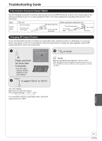
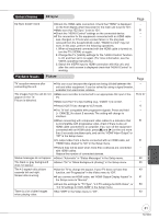
Troubleshooting Guide If the Antenna Connector Doesn't Match Use the following connection to suit the antenna lead to the unit's RF IN terminal, and the 75 coaxial cable to the antenna terminals on your TV or other equipment. Refer to the other equipment's operating instructions for more information. Type A twin lead This unit from the antenna (Flat) Twin lead 300 cable 300−75 transformer To this unit's RF IN terminal Other equipment (television etc.) 75−300 transformer 75 coaxial cable VHF or UHF Television Changing RF Output Channel If you connected this unit and a TV without an audio/video cable, interference (lines or patterning) or a very poor picture may appear on the TV. If this happens, follow the steps below to change the video playback channel (RF output channel) to remove the interference. RF Output Channel Press the channel up/down buttons to select a RF Output Channel. Ch. 3 Press and hold ENTER for more than 5 seconds. -The RF output channel number displays on the unit's display. TRACKING/V-LOCK to select "CH 3" or "CH 4". CH ENTER to finish. Notes When you set the RF output channel to "CH 3" or "CH 4" Video from this unit can be viewed on channels 3 and 4 on the TV. Press [VCR/TV] to switch to VCR mode and output video from this unit (¼ 6). The unit's display Each time you press the button: CH 3 (Default setting) CH 4 OFF For connections with the audio/video cable, set the RF output channel to "OFF". Reference 77 RQT8853
-
 1
1 -
2
-
3
-
4
-
5
-
6
-
7
-
8
-
9
-
10
-
11
-
12
-
13
-
14
-
15
-
16
-
17
-
18
-
19
-
20
-
21
-
22
-
23
-
24
-
25
-
26
-
27
-
28
-
29
-
30
-
31
-
32
-
33
-
34
-
35
-
36
-
37
-
38
-
39
-
40
-
41
-
42
-
43
-
44
-
45
-
46
-
47
-
48
-
49
-
50
-
51
-
52
-
53
-
54
-
55
-
56
-
57
-
58
-
59
-
60
-
61
-
62
-
63
-
64
-
65
-
66
-
67
-
68
-
69
-
70
-
71
-
 72
72 -
 73
73 -
 74
74 -
 75
75 -
 76
76 -
 77
77 -
 78
78 -
 79
79 -
 80
80 -
 81
81 -
 82
82 -
83
-
84
-
85
-
86
-
87
-
88
-
89
-
90
-
91
-
92
-
93
-
94
-
95
-
96
-
97
-
98
-
99
-
100
 |
 |
