Panasonic WVCW974 WVCW974 User Guide - Page 14
RS485 Communication Parameters (DIP Switch 1), Procedure to setup dip switch 1, Notes, Table-2
 |
UPC - 791871505373
View all Panasonic WVCW974 manuals
Add to My Manuals
Save this manual to your list of manuals |
Page 14 highlights
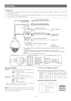
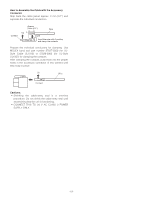
DIP Switch 1 ON 12345678 ON 12345678 ON 12345678 ON 12345678 ON 12345678 ON 12345678 ON 12345678 ON 12345678 ON 12345678 Unit Number 69 70 71 72 73 74 75 76 77 DIP Switch 1 ON 12345678 ON 12345678 ON 12345678 ON 12345678 ON 12345678 ON 12345678 ON 12345678 ON 12345678 ON 12345678 Unit Number 78 79 80 81 82 83 84 85 86 DIP Switch 1 ON 12345678 ON 12345678 ON 12345678 ON 12345678 ON 12345678 ON 12345678 ON 12345678 ON 12345678 ON 12345678 Unit Number 87 88 89 90 91 92 93 94 95 Notes: • When using the Unit Number "1 ~ 96" setting, the unit number setting needs to be configured using the RS485 SET UP menu. For details about configuring this setting, see step 2 on page 20. • Turning on power when this setting is selected causes the RS485 SET UP menu to appear during the initialization routine. ■ RS485 Communication Parameters (DIP Switch 1) Configuring DIP Switch 1 as shown below resets communication parameters to their factory default settings. You can then change the settings as desired. Table-2 DIP Switch 1 ON 12345678 ON 12345678 ON 12345678 ON 12345678 Setting Description This setting resets communication parameters to the factory default settings. BAUD RATE : 19 200 bit/s, DATA BIT : 8 bit, PARITY CHECK : NONE, STOP BIT : 1 bit BAUD RATE : 9 600 bit/s, DATA BIT : 8 bit, PARITY CHECK : NONE, STOP BIT : 1 bit BAUD RATE : 4 800 bit/s, DATA BIT : 8 bit, PARITY CHECK : NONE, STOP BIT : 1 bit ■ Procedure to setup dip switch 1 (1) Turn off the camera and use DIP Switch 1 to configure RS485 Communication Parameters as shown in Table-2. (2) Turn on the camera. This applies the setting you configured in step (1). (3) Turn off the camera, use DIP Switch 1 to set the unit number (as shown in Table-1), and then turn the camera back on again. -14-
-
 1
1 -
2
-
3
-
4
-
5
-
6
-
7
-
8
-
 9
9 -
 10
10 -
 11
11 -
 12
12 -
 13
13 -
 14
14 -
 15
15 -
 16
16 -
 17
17 -
 18
18 -
 19
19 -
20
-
21
-
22
-
23
-
24
-
25
-
26
-
27
-
28
-
29
-
30
-
31
-
32
-
33
-
34
-
35
-
36
-
37
-
38
-
39
-
40
-
41
-
42
-
43
-
44
-
45
-
46
-
47
-
48
-
49
-
50
-
51
-
52
-
53
-
54
-
55
-
56
-
57
-
58
-
59
-
60
-
61
-
62
-
63
-
64
-
65
-
66
-
67
-
68
-
69
-
70
-
71
-
72
-
73
-
74
-
75
-
76
-
77
-
78
-
79
-
80
-
81
-
82
-
83
-
84
-
85
-
86
-
87
-
88
-
89
-
90
-
91
-
92
-
93
-
94
-
95
-
96
-
97
-
98
-
99
-
100
-
101
-
102
-
103
-
104
-
105
-
106
-
107
-
108
-
109
-
110
-
111
-
112
-
113
-
114
-
115
-
116
-
117
-
118
-
119
-
120
-
121
-
122
 |
 |
