Panasonic WVCW974 WVCW974 User Guide - Page 18
Connections, Alarm In/Out Ratings, Alarm In, Alarm Out, Precautions, Accessory Connector Information
 |
UPC - 791871505373
View all Panasonic WVCW974 manuals
Add to My Manuals
Save this manual to your list of manuals |
Page 18 highlights
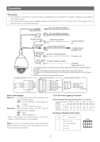
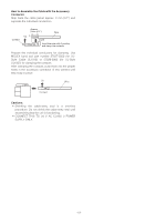
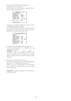
Connections Precautions • The following connections should be made by qualified service personnel or system installers in accordance with all local codes. • Turn off the power at the fuse box before starting the installation work, or it so could result in fire, electric shock, personal injury, and material damage. Separate 2-wire 24 V AC Cable for Heater 24 V AC Cable for camera 24 V AC RS485 Data Port Twisted Pair Cable*1 (RJ-12) Video Output Connector Coaxial Cable (5C-2V)*2 (BNC) Alarm Input Connector 8P Alarm Cable (provided) To Matrix Switcher, etc. To VIDEO IN port (CAMERA IN) To sensor, etc. RS485 Data Port Alarm Output Connector 4P Alarm Cable (provided) To buzzer, display device, etc. *1: For twisted pair cable, use shielded low-impedance cable with a thickness of at least AWG#22 (0.33 mm2). *2: Keep the overall length of coaxial cable under 1200 meters (in the case of 5C-2V). For details, see the operating instructions for the Panasonic system equipment you are going to connect. *3: Be sure to connect the grounding cable to ground. Alarm Input Connector Alarm Output Connector Data Tx Data Rx Red Orange Yellow Green (RJ-12) T(B) T(A) R(B) R(A) Alarm In 1 (Black) GND (Brown) Alarm In 2 (Red) GND (Orange) Alarm In 3 (Yellow) GND (Light Blue or Green) Alarm In 4 (Blue) GND (Violet) Alarm Out 1 (Grey) GND (White) Alarm Out 2 (Pink) GND (Light Green or Light Blue) Alarm In/Out Ratings Alarm In : 5 V DC pull-up input. Drive capacity of at lease 0.2 mA required. OFF : 4 V DC minimum 5 V DC maximum, or open ON : 1 V DC maximum or short Alarm Out : Open collector output. 16 V DC, 100 mA maximum drive capacity OFF : Open ON : 100 mA maximum * When connecting to an external device, set up the system so the ratings are not exceeded. Note: Do not turn off camera power within 30 seconds after turning it on. Doing so can cause pan, tilt, zoom, or focus to go out of position. • 24 V AC Power Supply Connection Recommended wire gauge sizes for 24 V AC line Copper wire size #24 #22 #20 #18 (AWG) (0.22mm2) (0.33mm2) (0.52mm2) (0.83mm2) Length (m) 20 of cable (approx.) (ft) 65 30 45 75 100 160 260 Accessory Connector Information Pin no. Power source 1 24 V AC LIVE 2 24 V AC NEUTRAL 3 Ground 4 Not use 43 21 -18-
-
 1
1 -
2
-
3
-
4
-
5
-
6
-
7
-
8
-
9
-
10
-
11
-
12
-
 13
13 -
 14
14 -
 15
15 -
 16
16 -
 17
17 -
 18
18 -
 19
19 -
 20
20 -
 21
21 -
 22
22 -
 23
23 -
24
-
25
-
26
-
27
-
28
-
29
-
30
-
31
-
32
-
33
-
34
-
35
-
36
-
37
-
38
-
39
-
40
-
41
-
42
-
43
-
44
-
45
-
46
-
47
-
48
-
49
-
50
-
51
-
52
-
53
-
54
-
55
-
56
-
57
-
58
-
59
-
60
-
61
-
62
-
63
-
64
-
65
-
66
-
67
-
68
-
69
-
70
-
71
-
72
-
73
-
74
-
75
-
76
-
77
-
78
-
79
-
80
-
81
-
82
-
83
-
84
-
85
-
86
-
87
-
88
-
89
-
90
-
91
-
92
-
93
-
94
-
95
-
96
-
97
-
98
-
99
-
100
-
101
-
102
-
103
-
104
-
105
-
106
-
107
-
108
-
109
-
110
-
111
-
112
-
113
-
114
-
115
-
116
-
117
-
118
-
119
-
120
-
121
-
122
 |
 |
