RCA F38310 User Guide & Warranty - Page 15
Audio, Speakers, COMPONENT VIDEO INPUT - remote
 |
UPC - 034909913192
View all RCA F38310 manuals
Add to My Manuals
Save this manual to your list of manuals |
Page 15 highlights
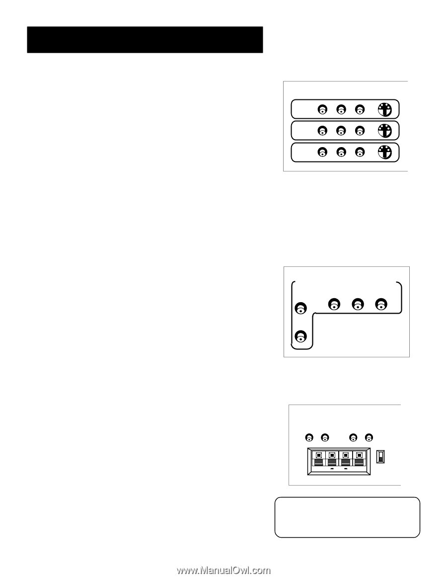
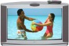
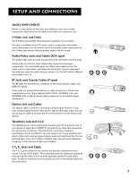
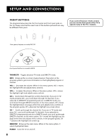
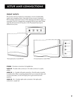
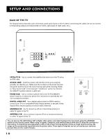
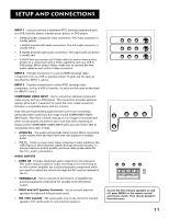
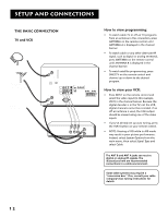
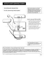
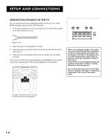
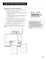
Setup and Connections INPUT 1 Lets you connect a baseband NTSC (analog) component such as a VCR, laserdisc player, Internet access device, or DVD player. • VIDEO provides composite video connection. The video connector is usually yellow. • L AUDIO provides left audio connection. The left audio connector is usually white. • R AUDIO provides right audio connection. The right audio connector is usually red. • S-VIDEO lets you connect an S-Video cable for better video quality picture to a component with S-Video capability, such as a VCR or DVD player. When using S-Video, make sure to connect the two audio cables as well as the S-Video connector. INPUT 2 Provides connection to a second NTSC (analog) video component such as a VCR or laserdisc player. Its jacks are the same as described for INPUT 1, above. INPUT 3 Provides connection to a third NTSC (analog) video component, such as a VCR or laserdisc. Its jacks are the same as described for INPUTS 1 and 2. COMPONENT VIDEO INPUT Use to connect an optional component video source, such as a DVD player. This connection provides optimum quality. Note that it is essential to match the color coded connectors between a compatible device and the monitor. Grey side panels protecting against screen burn-in are not always generated when watching a 4:3 image via the COMPONENT VIDEO INPUT jacks. Therefore, limited viewing of a 4:3 image is recommended when no side panels are present. Also note that when watching an image via the COMPONENT VIDEO INPUT jacks, you will not be able to manipulate the screen format. • AUDIO R/L The audio jacks provide stereo sound. When connected, audio volume from the main front and rear speakers is variable audio. • Y PB PR Unlike a single video input, component video maintains the video signal as three separate signals through these three jacks. To ensure maximum picture quality, use three video-grade cables for the Y, P , and P connections. B R AUDIO OUTPUTS • FIXED L/R Provides fixed-level audio output from the television. This audio output is ideal for audio recording or for connecting to an A/V receiver amplifier (an auxiliary baseband component) when you want to control the volume through the A/V receiver instead of the TV. • VARIABLE L/R Use to connect an A/V receiver or amplifier (an auxiliary baseband component) for variably-controlled stereo output. • RIGHT and LEFT Speaker Terminals Use to connect external speakers for right and left surround sound. • INT. / EXT. (switch) INT sends audio only to the monitor's internal speakers. EXT sends audio to only external speakers. AUDIO VIDEO L R INPUT1 S-VIDEO INPUT2 INPUT3 COMPONENT VIDEO INPUT AUDIO R Y PB PR L AUDIO OUTPUTS FIXED VARIABLE LR LR EXT SPEAKERS EXT + + INT R L To turn the TV's internal speakers on and off, press MENU on the remote control and choose Audio. Then choose Speakers from the menu. 11
-
 1
1 -
2
-
3
-
4
-
5
-
6
-
7
-
8
-
9
-
 10
10 -
 11
11 -
 12
12 -
 13
13 -
 14
14 -
 15
15 -
 16
16 -
 17
17 -
 18
18 -
 19
19 -
 20
20 -
21
-
22
-
23
-
24
-
25
-
26
-
27
-
28
-
29
-
30
-
31
-
32
-
33
-
34
-
35
-
36
-
37
-
38
-
39
-
40
-
41
-
42
-
43
-
44
-
45
-
46
-
47
-
48
-
49
-
50
-
51
-
52
-
53
-
54
-
55
-
56
-
57
-
58
-
59
-
60
-
61
-
62
-
63
-
64
-
65
-
66
-
67
-
68
-
69
-
70
-
71
-
72
-
73
-
74
-
75
-
76
-
77
-
78
-
79
-
80
-
81
-
82
-
83
-
84
-
85
-
86
-
87
-
88
-
89
-
90
-
91
-
92
-
93
-
94
-
95
-
96
-
97
-
98
-
99
-
100
 |
 |