Rheem RARL-JEC Installation Instructions - Page 12
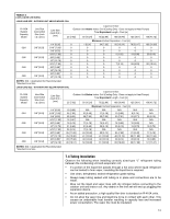
Maximum Length of Lines, 3 Outdoor Unit Installed Above or Below Indoor Coil
 |
View all Rheem RARL-JEC manuals
Add to My Manuals
Save this manual to your list of manuals |
Page 12 highlights
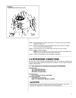
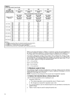
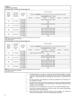
TABLE 3 VAPOR LINE CAPACITY MULTIPLIER (-)ARL Unit Vapor Line Connection Size (inches I.D.) [mm] Vapor Line Run Feet [m] Opt. 25' [7.62] Std. Opt. Opt. 50' [15.24] Std. Opt. Opt. 75' [22.86] Std. Opt. Opt. 100' [30.48] Std. Opt. Opt. 125' [38.10] Std. Opt. Opt. 150' [45.72] Std. Opt. 024 3/4" [19.05] I.D. Sweat 5/8" [15.88] Optional 3/4" [19.05] Standard - 1.00 1.00 N/A 0.99 1.00 N/A 0.98 0.99 N/A 0.97 N/A N/A 0.97 N/A N/A 0.96 N/A N/A 036 048 7/8" [22.23] I.D. Sweat 7/8" [22.23] I.D. Sweat Vapor Line Diameter (inches O.D.) [mm] 5/8" [15.88] Optional 5/8" [15.88] Optional 3/4" [19.05] Standard 3/4" [19.05] Standard - 7/8" [22.23] Optional 0.98 0.98 1.00 1.00 N/A 1.02 0.96 0.96 0.99 0.99 N/A 1.00 0.96 0.94 0.98 0.98 N/A 1.00 0.94 0.92 N/A 0.98 N/A N/A 0.93 0.90 N/A 0.97 N/A N/A 0.92 0.88 N/A 0.96 N/A N/A NOTES: 1. Do NOT exceed the limits in the liquid and suction line sizing charts. 2. Do NOT use 7/8 OD suction lines in 2 or 3-ton applications. 3. Do NOT use 1-1/8 OD suction line in ANY application. 4. 2 and 3-ton line sets over 75 feet MUST use the optional suction line. 060 7/8" [22.23] I.D. Sweat 3/4" [19.05] Optional 7/8" [22.23] Standard - 0.99 1.00 N/A 0.97 0.99 N/A 0.96 0.99 N/A 0.95 0.98 N/A 0.94 0.97 N/A 0.93 0.97 N/A Refer to Line Size Information in Tables 3, 4 and 5 for correct size and multipliers to be used to determine capacity for various vapor line diameters and lengths of run. The losses due to the lines being exposed to outdoor conditions are not included. The factory refrigeration charge in the outdoor unit is sufficient for 15 feet of interconnecting lines. The factory refrigeration charge in the outdoor unit is sufficient for the unit and 15 feet of standard size interconnecting liquid and vapor lines. For different lengths, adjust the charge as indicated below. 1/4" ± .3 oz. per foot 5/16" ± .4 oz. per foot 3/8" ± .6 oz. per foot 1/2" ± 1.2 oz. per foot 7.2 Maximum Length of Lines The maximum length of interconnecting line is 150 feet. Always use the shortest length possible with a minimum number of bends. Additional compressor oil is not required for any length up to 150 feet. NOTE: Excessively long refrigerant lines cause loss of equipment capacity. 7.3 Outdoor Unit Installed Above or Below Indoor Coil Use the following guidelines when installing the unit: 1. Expansion Valve Coil: a. The vertical separation cannot exceed the value in Tables 4 and 5. b. No changes are required for expansion valve coils. 2. It is recommended to use the smallest liquid line size permitted to minimize the system charge. 3. Tables 4 and 5 may be used for sizing horizontal runs. 12
-
 1
1 -
2
-
3
-
4
-
5
-
6
-
 7
7 -
 8
8 -
 9
9 -
 10
10 -
 11
11 -
 12
12 -
 13
13 -
 14
14 -
 15
15 -
 16
16 -
 17
17 -
18
-
19
-
20
-
21
-
22
-
23
-
24
-
25
-
26
-
27
-
28
-
29
-
30
-
31
-
32
-
33
-
34
-
35
-
36
-
37
-
38
-
39
-
40
-
41
-
42
-
43
-
44
-
45
-
46
-
47
-
48
 |
 |
