Rheem RARL-JEC Installation Instructions - Page 33
Electrical Wiring
 |
View all Rheem RARL-JEC manuals
Add to My Manuals
Save this manual to your list of manuals |
Page 33 highlights
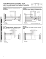
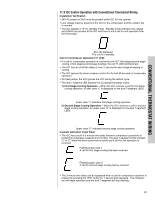
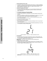
12.0 ELECTRICAL WIRING Field wiring must comply with the National Electric Code (C.E.C. in Canada) and any applicable local code. 12.1 Power Wiring It is important that proper electrical power from a commercial utility is available at the condensing unit contactor. Voltage ranges for operation are shown in Table 7. Install a branch circuit disconnect within sight of the unit and of adequate size to handle the starting current (see Table 1). Power wiring must be run in a rain-tight conduit. Conduit must be run through the connector panel below the access cover (see Figure 1) and attached to the bottom of the control box. Connect power wiring to contactor located in outdoor condensing unit electrical box. (See wiring diagram attached to unit access panel.) Check all electrical connections, including factory wiring within the unit and make sure all connections are tight. DO NOT connect aluminum field wire to the contactor terminals. TABLE 7 VOLTAGE RANGES (60 HZ) Nameplate Voltage 208/230 (1 Phase) Operating Voltage Range at Copeland Maximum Load Design Conditions for Compressors 197 - 253 12.2 Grounding A grounding lug is provided near the contactor for a ground wire. ! WARNING THE UNIT MUST BE PERMANENTLY GROUNDED. FAILURE TO DO SO CAN CAUSE ELECTRICAL SHOCK RESULTING IN SEVERE PERSONAL INJURY OR DEATH. 12.3 Control Wiring If the low voltage control wiring is run in conduit with the power supply, Class I insulation is required. Class II insulation is required if run separate. Low voltage wiring may be run through the insulated bushing provided in the 7/8 hole in the base panel, up to and attached to the pigtails from the bottom of the control box. Conduit can be run to the base panel if desired by removing the insulated bushing. A thermostat and a 24 volt, 40 VA minimum transformer are required for the control circuit of the condensing unit. The furnace or the air handler transformer may be used if sufficient. See the wiring diagram for reference. Use Table 6 to size the 24 volt control wiring. 33
-
 1
1 -
2
-
3
-
4
-
5
-
6
-
7
-
8
-
9
-
10
-
11
-
12
-
13
-
14
-
15
-
16
-
17
-
18
-
19
-
20
-
21
-
22
-
23
-
24
-
25
-
26
-
27
-
 28
28 -
 29
29 -
 30
30 -
 31
31 -
 32
32 -
 33
33 -
 34
34 -
 35
35 -
 36
36 -
 37
37 -
 38
38 -
39
-
40
-
41
-
42
-
43
-
44
-
45
-
46
-
47
-
48
 |
 |
