Rheem RARL-JEC Installation Instructions - Page 27
Conventional Thermostat Wiring
 |
View all Rheem RARL-JEC manuals
Add to My Manuals
Save this manual to your list of manuals |
Page 27 highlights
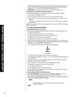
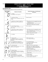
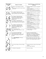
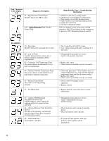
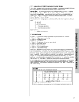
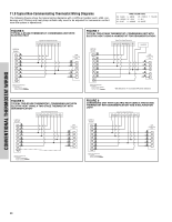
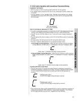
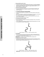
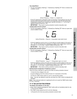
CONVENTIONAL THERMOSTAT WIRING 11.7 Conventional 24VAC Thermostat Control Wiring The (-)ARL series of heat pumps allow the installer to use conventional 24VAC control wiring and a conventional thermostat for proper unit operation. IMPORTANT: The preferred method of unit installation and operation is with the Comfort Control2 System™. The Comfort Control2 System™ allows access to the fault history of the system. This diagnostic information is not available when the (-)ARL unit is using a conventional thermostat. Reference section 11.2 Comfort Control2 System™ Control Wiring. Thermostat control wiring requires a minimum of four (4) wires for proper unit operation: R - 24VAC C - 24VAC common Y1 - First stage operation Y2 - Second stage operation Optional wiring: L - ICC fault information L Terminal Output • Flash 1 - Compressor running extremely long run cycle or low pressure • Flash 2 - High pressure control trip • Flash 3 - Unit short cycling • Flash 4 - Locked rotor • Flash 5 - Compressor will not run, open circuit • Flash 6 - Open start circuit • Flash 7 - Open run circuit • Flash 8 - Control mis-operation • Flash 9 - Low control voltage When the L terminal from the outdoor unit is connected to a conventional thermostat that is L terminal compatible, the thermostat display will flash the above codes. If the low voltage control wiring is run in conduit with the power supply, Class I insulation is required. Class II insulation is required if run separate. Low voltage wiring may be run through the insulated bushing provided in the 7/8 hole in the base panel, up to and attached to the pigtails from the bottom of the control box. Conduit can be run to the base panel if desired by removing the insulated bushing. A thermostat and a 24-volt, 40VA minimum transformer are required for the control circuit of the condensing unit. The furnace or the air handler transformer may be used if sufficient. See the wiring diagram for reference. Use Table 6 to size the 24volt control wirings. TABLE 6 FIELD WIRE SIZE FOR 24 VOLT THERMOSTAT CIRCUITS Thermostat Load - Amps SOLID COPPER WIRE - AWG. 3.0 16 14 12 10 10 10 2.5 16 14 12 12 10 10 2.0 18 16 14 12 12 10 50 100 150 200 250 300 Length of Run - Feet (1) (1) Wire length equals twice the run distance. NOTE: Do not use control wiring smaller than No. 18 AWG between thermostat and outdoor unit. 27
-
 1
1 -
2
-
3
-
4
-
5
-
6
-
7
-
8
-
9
-
10
-
11
-
12
-
13
-
14
-
15
-
16
-
17
-
18
-
19
-
20
-
21
-
 22
22 -
 23
23 -
 24
24 -
 25
25 -
 26
26 -
 27
27 -
 28
28 -
 29
29 -
 30
30 -
 31
31 -
 32
32 -
33
-
34
-
35
-
36
-
37
-
38
-
39
-
40
-
41
-
42
-
43
-
44
-
45
-
46
-
47
-
48
 |
 |
