Rheem RARL-JEC Installation Instructions - Page 16
Hard Start Components, 0 High And Low Pressure Controls, Hpc And Lpc
 |
View all Rheem RARL-JEC manuals
Add to My Manuals
Save this manual to your list of manuals |
Page 16 highlights
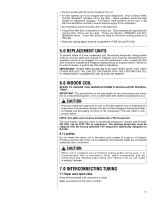
• Once the compressor turns off, the crankcase heater control (CCH) begins the two-hour timer countdown. • If the compressor stays off for two hours, the CCH turns on the crankcase heater. All heaters are located on the lower half of the compressor shell. Its purpose is to drive refrigerant from the compressor shell during long off cycles, thus preventing damage to the compressor during start-up. At initial start-up or after extended shutdown periods, make sure the heater is energized for at least 12 hours before the compressor is started. (Disconnect switch on and wall thermostat off.) 9.0 HARD START COMPONENTS Factory-installed start components are standard on all models. 10.0 HIGH AND LOW PRESSURE CONTROLS 10.0 (HPC AND LPC) These controls keep the compressor from operating in pressure ranges which can cause damage to the compressor. Both controls are in the low voltage control circuit. High pressure control (HPC) is an automatic-reset which opens near 610 PSIG and closes near 420 PSIG. The low pressure control (LPC) is an automatic-reset which opens near 15 PSIG and closes near 40 PSIG. NOTE: HPC and LPC are monitored by the Comfort Control2. See Section 12.0. ! CAUTION THE COMPRESSOR HAS AN INTERNAL OVERLOAD PROTECTOR. UNDER SOME CONDITIONS, IT CAN TAKE UP TO 2 HOURS FOR THIS OVERLOAD TO RESET. MAKE SURE OVERLOAD HAS HAD TIME TO RESET BEFORE CONDEMNING THE COMPRESSOR. 10.1 Evacuation Procedure Evacuation is the most important part of the entire service procedure. The life and efficiency of the equipment is dependent upon the thoroughness exercised by the serviceman when evacuating air and moisture from the system. Air in the system causes high condensing temperatures and pressure, resulting in increased power input and non-verifiable performance. Moisture chemically reacts with the refrigerant and oil to form corrosive hydrofluoric and hydrochloric acids. These attack motor windings and parts, causing breakdown. After the system has been leak checked and proven sealed, connect the vacuum pump and evacuate system to 500 microns. The vacuum pump must be connected to both the high and low sides of the system through adequate connections. Use the largest size connections available since restrictive service connections may lead to false readings because of pressure drop through the fittings. IMPORTANT: Compressors (especially scroll type) should never be used to evacuate the air conditioning system because internal electrical arcing may result in a damaged or failed compressor. With thermostat in the "Off" position, turn the power on to the furnace and the heat pump. Start the heat pump and the furnace with the thermostat. Make sure the blower is operating. 16
-
 1
1 -
2
-
3
-
4
-
5
-
6
-
7
-
8
-
9
-
10
-
 11
11 -
 12
12 -
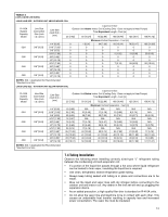 13
13 -
 14
14 -
 15
15 -
 16
16 -
 17
17 -
 18
18 -
 19
19 -
 20
20 -
 21
21 -
22
-
23
-
24
-
25
-
26
-
27
-
28
-
29
-
30
-
31
-
32
-
33
-
34
-
35
-
36
-
37
-
38
-
39
-
40
-
41
-
42
-
43
-
44
-
45
-
46
-
47
-
48
 |
 |